Technical Swapping Electrical Heated Leather Seats Help

Currently reading:
Technical Swapping Electrical Heated Leather Seats Help

Joined
Mar 13, 2006
Messages
84
Points
93
Location
W.London, Feltham
Hi i just purchased a second stilo which has electric heated leather seats and i want to put them into my other stilo, both cars are of the same year (2002) and both are 1.8 Dynamic's, i have removed all the seats and i have come across an extra Blue connector from the floor wiring does that connector power the seats and provide the heating to them?
If so is there any easy way to swap that wire and connector?
Because i followed the wiring under the carpet to the front of the centre dash and lost it and it just looks a nightmare to strip out. If anyone could help i would be really grateful.
 
Never had mine apart yet but the wiring diagram shows 3 connectors for the 4 motors for each seat that connect directly to the seat switch panels/ECU. They are:

H66A & H67A Blue 9 pin
H66B & H67B White 6 pin
H66C & H67C Black 12 pin


For the heated seat elements, it shows as white 6 pin connectors D70 & D71

On the wiring diagrams:
B45 is the rear fuse box.
H66 & H67 are the Switch panels/ECU.

Although the wiring diagram shows 2 fuses in the rear fuse box (B45) there are no fuses in mine. I suspect there's cut-outs in the seat ECUs

White connectors D70 & D71 provide power to the seat motors and heaters. I've no idea where an extra blue connector would go.
 

Attachments

  • Elec Seat 1.JPG
    Elec Seat 1.JPG
    88.2 KB · Views: 215
  • Elec Seat 2.JPG
    Elec Seat 2.JPG
    59.4 KB · Views: 159
  • Heated Seats.JPG
    Heated Seats.JPG
    71.6 KB · Views: 171
Thanks Davren, this is the image of the connectors on the other car i want to install the seats to;
IMG_0143.jpg

And this is the image of the connectors on the electrical seats ;
IMG_0146.jpg
Would anyone know how to get the wiring from the blue connector and where it actually goes?
 
Last edited:
When you say blue connector, do you mean the black one in your 2nd picture with the blue locking bar or a completely blue connector somewhere else?

Also, as the seat ECUs are connected to the CAN system, fitting electric seats into a car with a body computer designed for normal seats may give you continuous warning beeps and messages.

Yes Davren sorry its the blue and black connector, I just need to know where it goes, either a fuse box or the main terminal on the battery, I can take the can from the other car if required, I'm just lost :(
 
How many possible contacts has the connector and how many and what colour wires are fitted each side of it?

Both 6 Contact Points:

Passenger Side;
Pink & White
Grey
Black & Red (thick)
Black (thick)
Black & Pink
Black

Drivers Side;
Black (thick)
Black & Pink
Black
Red & Yellow (thick)
Black & White
Pink & White
 
So... if the two 6 pin connectors have the colours you've posted above one side of each connector, what colours are the other side of each connector?

Drivers side under the seat;

white & light orange
blue & brown
red & green
2 solid black in one socket
black & light pink
black

Passenger side under seat;

white & light pink
brown & blue
red & green
2 solid black in one socket
black & light pink
black
 
This is the best diagram i could do :D As before i just want to know where these wires go, is it a certain fuse box or a switch etc ;

You've still not shown all the wires that go into and out of each connector. Wiring colours will often change each side of the connectors and if I'm going to trawl through pages of wiring diagrams for you, you need to give me all the information I've asked for.

Also, where you've written, for example, "Pink & White", does it mean 1 pink wire and 1 white wire, or 1 pink wire with a white tracer line on it? For I pink wire and 1 white wire, write Pink + White, for a pink wire with a white tracer, write Pink/White.

You may need to disconnect each connector to see the individual pin numbers inside.

If you give me all the information, I'll try to get an answer for you,
 
I've found some of the wires that match your connectors but the wiring diagrams show some of them as different colours. I think yours is going to be the same as mine and the wiring diagrams don't match what's actually in our cars.

Can you look in the rear fuse box of your donor car to see whether it has fuses F57 and F67 fitted. Also whether there's a relay there, and if so, what colour wires go to which pins on it. The pin numbers will be marked on the bottom of the relay and will be 85, 86, 87 and 30.

Here's a diagram of the rear fuse box.
.
 

Attachments

  • Rear Fuse Box.JPG
    Rear Fuse Box.JPG
    80.7 KB · Views: 745
Yeah, yours does have the fuses. It's the two red 10 Amp fuses next to each other if you match it up with the handbook diagram I posted.

While you've got it open, post the colours of all the wires that go under the fuse box.

Doesn't matter about the wires that go to the connector top left of your picture or the green and blacks that go to the bolt on earthing connector box bottom right.
 
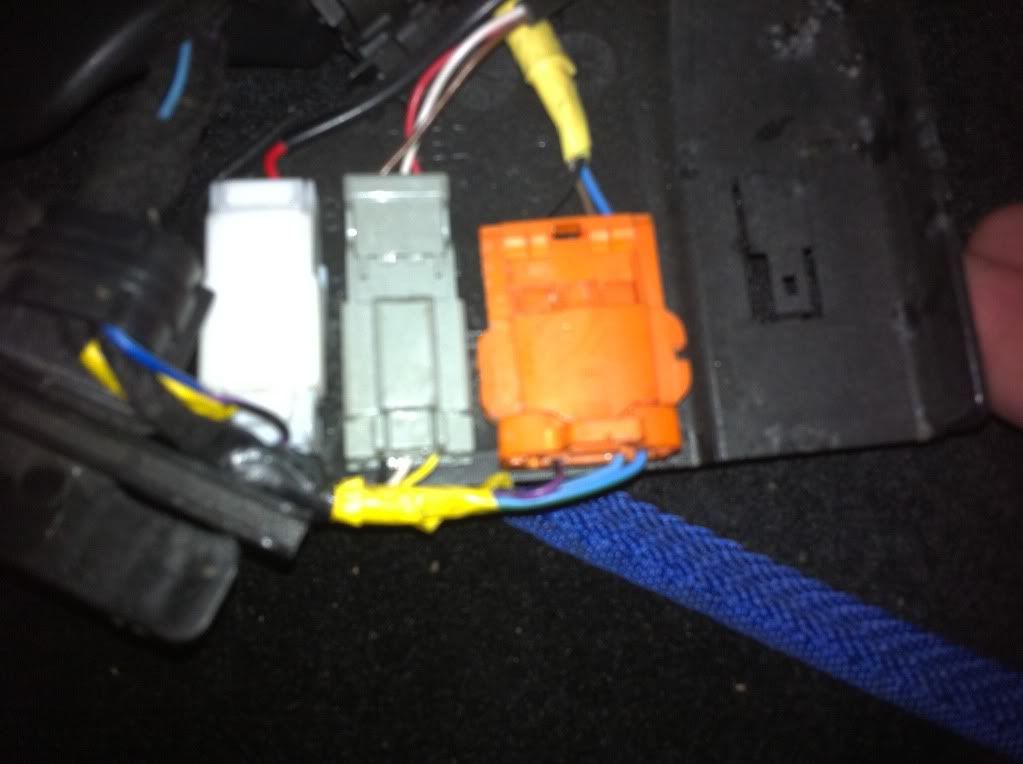
Your wiring more or less follows the diagrams I posted in post #2 above except some of the colours in your car are different.

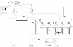
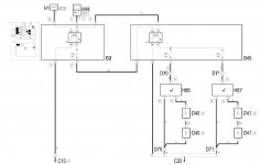
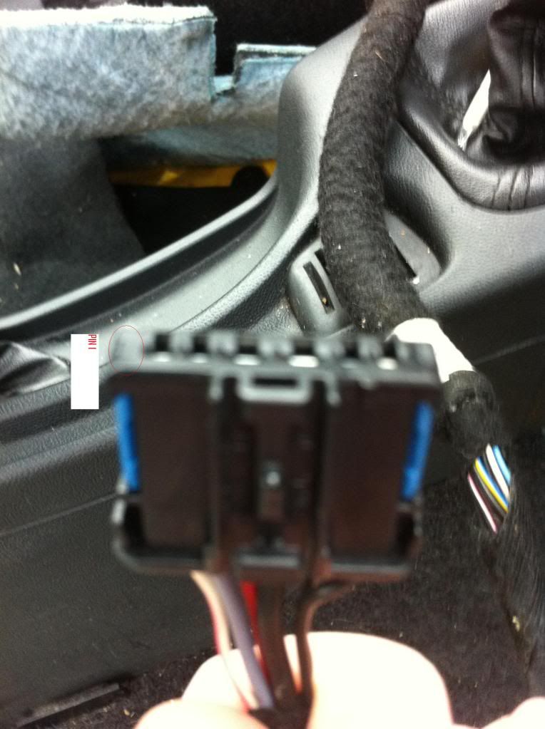
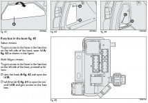
Referring to the wiring diagrams, the black/blue connectors are D71 for the passenger side and D70 for the driver side. The numbers printed in boxes next to D71 and D70 are the pin numbers in the connectors.

The letters printed next to the wires in the diagrams are Italian initial letters for the colours of the wires as follows:

A = Light Blue
B = White
C = Orange
G = Yellow
H = Grey
L = Dark Blue
M = Brown
N = Black
R = Red
S = Pink
V = Green
S = Pink

Wires with a main colour and a tracer colour are shown as e.g. RN (Red/Black), RG (Red/Yellow), BS (White/Pink), NS (Black/Pink), NB (Black/White) etc. Convention is to write the main colour first and the tracer colour second but Italian wiring diagrams don't always follow convention.

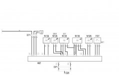
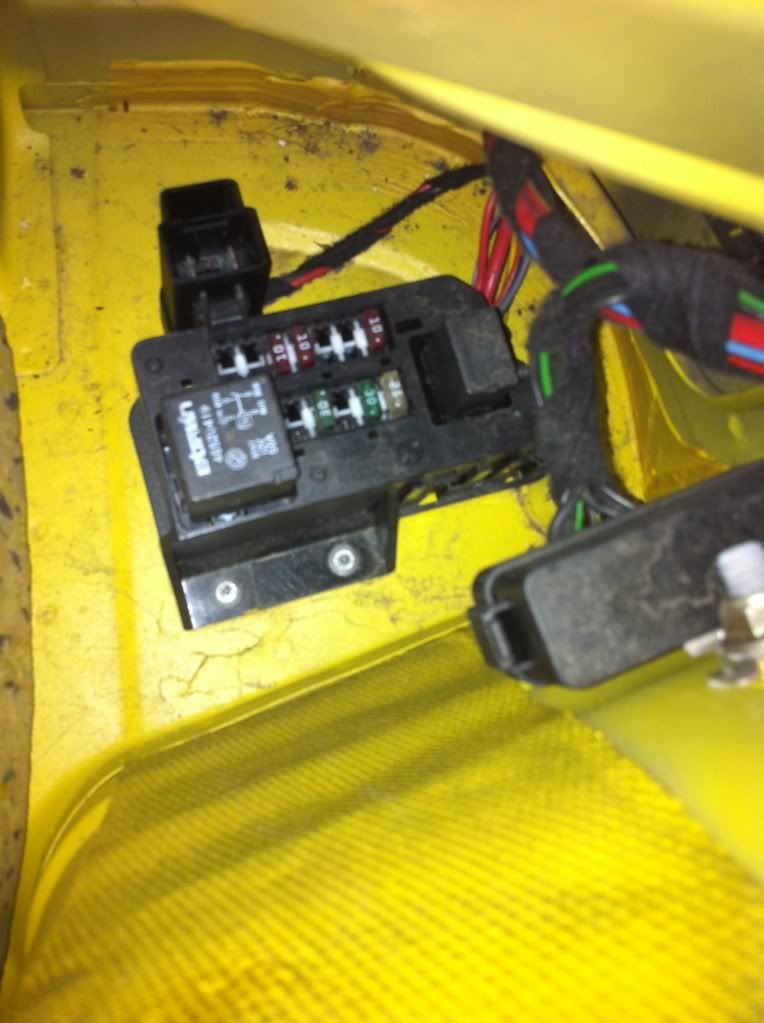
The seat motors get power from fuses F56 and F60, both 30 Amp green fuses in the rear fuse box (B45).
The seat heaters get power from fuses F57 and F67, both 10 Amp red fuses in the rear fuse box (B45).
All 4 fuses are supplied by the large black 50 Amp relay in the rear fuse box.

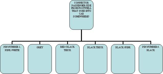
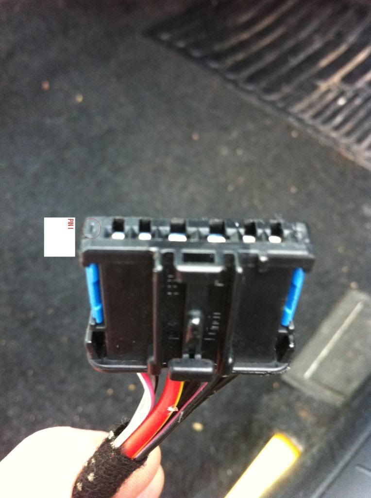
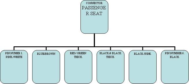
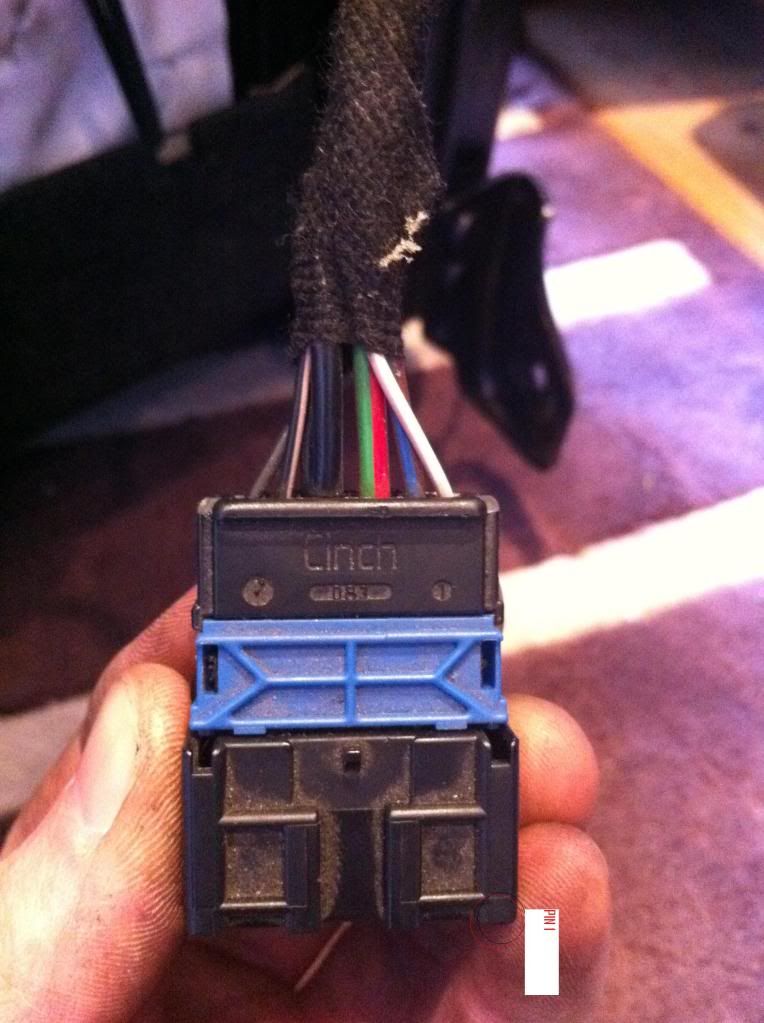
The wires from your passenger side black/blue connector (D71) go to:

Pin 1 (White/Pink) CAN line.*
Pin 2 (Grey) to the rear fuse box (B45) pin 6 and connects to fuse F67.
Pin 3 (Red/Black) to B45 pin 10 and connects to fuse F60.
Pin 4 (Black) to the passenger side earth connection (C20)
Pin 5 (Black/Pink) CAN line.*
Pin 6 (Black) to earth connection C20


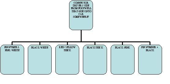
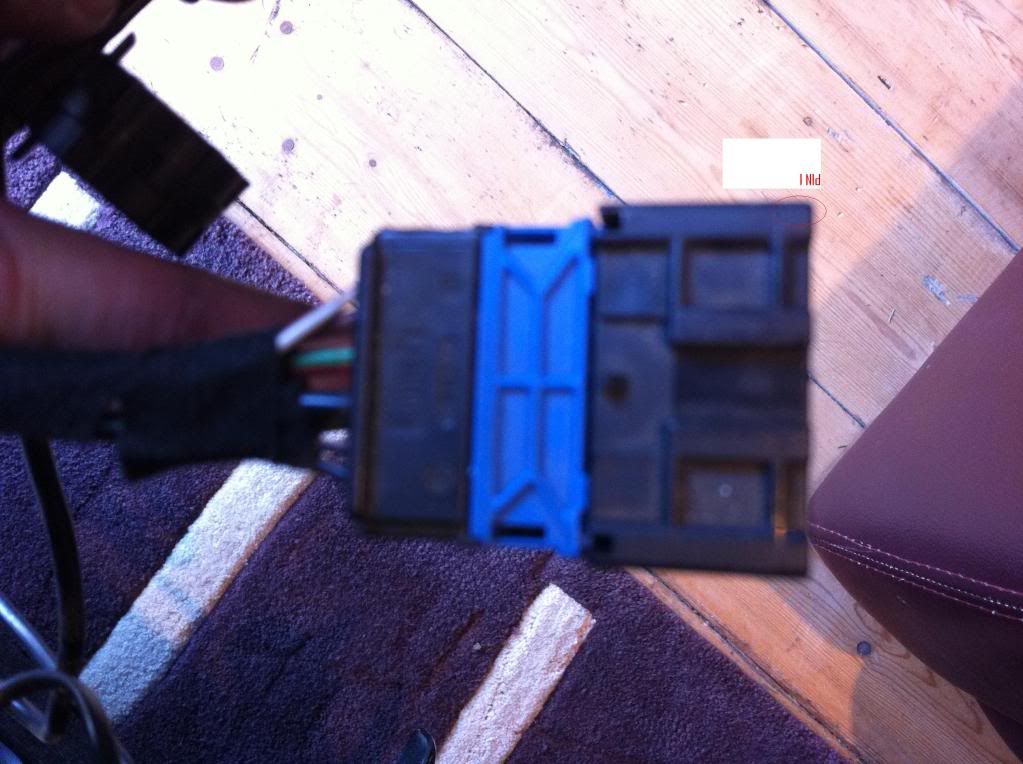
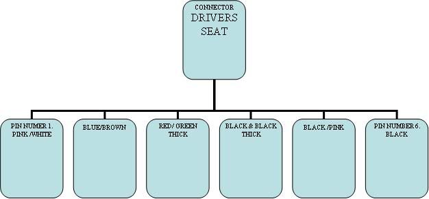
The wires from your driver side black/blue connector (D70) go to:

Pin 1 (White/Pink) CAN line.*
Pin 2 (Black/White) to the rear fuse box (B45) pin 7 and connects to fuse F57.
Pin 3 (Red/Yellow) to B45 pin 12 and connects to fuse F56.
Pin 4 (Black) to passenger side earth connection (C20)
Pin 5 (Black/Pink) CAN line. *
Pin 6 (Black) to driver side facia earth connection (C15)

The four power supply wires (Grey, Red/Black, Black/White and Red/Yellow) will be the wires with the same colours that you posted at the rear fuse box. (you posted Black/Grey, it will probably be Black/White) You will probably need to swap the complete rear fuse box from your donor car.

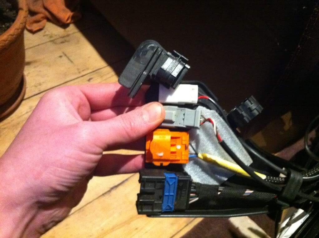
If it isn't already there, you will also need a thick red wire capable of carrying at least 50 Amps to supply pin 1 of the rear fuse box from the engine fuse box (B2). From your photo, it looks as though there is a thick red wire.

You could connect all 4 of the black earth wires to any convenient earth point if it's easier than running them to earth connections C15 and C20.

* The wiring diagram doesn't show where the 4 CAN lines are connected. You may not need to connect them at all, but if you do, they can be connected to the same colour CAN lines anywhere in the car.
 
Davren, you sir are a genius thank you :worship: Now i could tackle this myself :confused: or an auto electrician, would there be anyone within this forum whom could assist within the London area? i would pay generously.

Thanks again :D
 
Finally project is completed, if anyone is interested I can help with a guide of some sort but I didn't take pictures as I set a day to do it and took longer than I thought it would.
 
Re: Humor me, abarth clocks in a dynamic?

EDIT: where are the controls for the heated/elec seats?

Seat switches are on the side of the seats.

Two lever switches for horizontal and vertical movement. Buttons for seat heaters and lumbar adjistment and three memory positions on the driver's seat to preset the seats and door mirrors for different size drivers.
.
 

Attachments

  • Seat Switches.jpg
    Seat Switches.jpg
    237.7 KB · Views: 57
Re: Humor me, abarth clocks in a dynamic?

do your memory buttons work on the retro fitted seats?

Memory function for the seat should work because the ECU that controls it is built into the switch.

Memory function for the mirrors may be a problem unless memory mirrors are also fitted. There's different part numbers for the mirrors fitted to cars with electric seats.
 
Last edited:
Back
Top