Technical P0105 & p0340

Currently reading:
Technical P0105 & p0340

So i got my brother to help me with this as i haven't got a clue how to use a multi meter! He tested it as you said and said there was no resistance at all so he didn't bother to test the 5v as he said the sensor must be broken.

Next question, how easy is it to change this sensor, as getting to it from under the car isn't the easiest thing so i'm guessing changing it won't be easy either...
 
Well, near zero resistance actually means the circuit is good, ie there is little resistance to those magic little electrons flowing. Imagine a water pipe with very little resistance to water flow so that's good. If you can't get a resistance measurement ie near infinite resistance then that's bad, the circuit path is blocked. Some multimeters have a circuit testing setting and beeps if the circuit you're testing is good with no or low resistance. That's pretty easy to use

It would be worth getting a 2nd opinion before diving in to change the CMPS. If there's a problem with the 5v supply or earth then you'd be wasting your time and the fact you have MAP sensor fault codes coming up too then it looks more like a circuit problem than a component failure but it could even be the MAP sensor itself throwing everything out and dragging the CMPS down with it

So you really need to have both MAP and CMPS circuits checked for continuity and then checked for 5v and earth supply. If you've got that then you need to check the earth shield wire and then check the signals from both sensors. Really not difficult for a decent electrician but it might be worth finding a good one to check it out for you

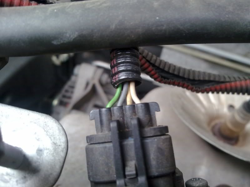
If you need to, then you get to the camshaft sensor itself from the top, it's just the connector that is half way down the engine front
 
Last edited:
How abouts would i find the actual sensor? I don't really want to go under the car again as its filthy! I don't know if he meant there was no resistance or i misheard but he definately said the sensor wasn't working as the meter didn't read anything.

I'll ask him again tomorrow, failing that, would i have to go to fiat to fix this or would any garage be able to do the job?
 
cam angle sensor 2.JPG
It's next to the camshaft sprocket on the top side of the engine
BUT there may not be anything wrong with it and it really needs some further investigations on the circuit as to why the car is putting up fault codes for it and the MAP sensor
 
Last edited:
So i've asked my brother again and what he actually meant was that it had a high resistance/infinite and that the circuit was open.

What we did was remove the ECU B connector and tested them from the number 43 and 7 pins and then tested them while the ECU was plugged back in. My brother's pretty good with electronics so i believe him.

How would we test the MAP sensor and also for the 5v? Is the MAP sensor the black connector next to the white one?

The CMPS sensor has an open circuit so what does that mean? Sorry for all the questions but its beginning to be a pain to drive the stilo...
 
Open circuit is bad news and means there's no circuit. If you tested it at the ECU pns then that's good but i would also test directly at the white connector as bad contacts there would produce open circuit too and CMPS don't often fail

5v and earth arrives at the MAP sensor from the ECU. Check your wiring diag for wire colors and pin numbers
The black connector next to the white one you've been working on is the crank/rpm sensor.

MAP 1.2.JPG
Your MAP sensor is up the top of the engine on the intake. Do you have elearn? If not then time to get one. MAP has 4 wires
pin 1 5v
pin 2 air temp signal
pin 3 earth
pin 4 MAP signal
 
Last edited:
I do have a elearn cd somewhere. What should i be looking for on there?

And what should i be testing the MAP sensor for? With the white connector, do i leave it connected and test it or disconnect and test? Theres 3 pins but i don't know which one to check.

BTW, you're a legend for helping mate. And you deserve a drink after this! (y)
 
Ok concentrating on the CMPS white connector we are looking for continuity, a circuit, a low resistance so with power off, disconnect the white conector and check the two outer pins resistance. No figure at all means no circuit and there is break in the wiring or the CMPS is finished and needs replacing

cam angle and MAP sensors 4.JPG
With the MAP then initially check for 5v supplied to pin D (grey wire) with ignition on as this is also the supply for the CMPS.

MAP sensor 3.JPG
Just push the multimeter pos probe into the back of the connector like this
 
Last edited:
So i'm a little confused with the wiring diagram and colours.

Heres my map sensor:

23052011189.jpg


Do i still test the 2 outside wires as you mention pin D as the 5v but pin D is white on the connector. Also, my probe is too big to squash down the side of the wire. I haven't tested the CMPS as its been pouring again so i've been putting it off however i really need to get this sorted. Having no acceleration is dangerous getting out of junctions!
 
You're not reading the post properly and getting confused which connector

CMPS WHITE CONNECTOR
Ok concentrating on the CMPS white connector we are looking for continuity, a circuit, a low resistance so with power off, disconnect the white conector and check the two outer pins resistance.
So what does this mean? No figure at all, infinite resistance means no circuit and there is break in the wiring or the CMPS is finished and needs replacing. If you have a very low reistance then there is a circuit ie no broken wires or broken internal circuit so that looks promising

MAP SENSOR
If your probe is too big then use a pin to back probe the connector and connect to that. 5v should be suppplied to pin D which is marked on the sensor if you look closely and is the grey wire
So what does this tell you? That the ECU is putting out 5v to the MAP sensor and this is on the same supply line as the CMPS

If that's ok then go back the CMPS white connector and see if 5v is being supplied there also to its pin 1 - again grey wire
 
Last edited:
I really appreciate your patience Decks. Do i just connect the other probe to any earth source or do i have to connect it to a certain position?

I want to test the MAP sensor as thats easier to check first.

A previous post says :
Pin 1 - 5V
Pin 2 - Air Temp
Pin 3 - Earth
Pin 4 - MAP signal

But the wiring diagram is:
A - Earth
B - Air Temp
C - MAP signal
D - 5V

If i only need pin D and an earth source then thats ok and i'll figure it out from there. Its bank holiday weekend so i think the only time i'll be able to work on this is sunday.
 
The previous post was for a 1.2 engine type MAP where the pins have numbers

Your pins are lettered so yours is as the wiring diagram
A - Earth
B - Air Temp
C - MAP signal
D - 5V reference

Battery earth will be fine for comparing to earth as your other probe contact

MAP signal will be around 4.5v with ignition on and engine off but really you just want to check if the 5v reference is there then go on to check it is arriving the same at the CMPS
 
So i woke up 7am to try and investigate and its started raining. Great. Anyways, i've tested the MAP sensor and there's definately no 5v getting through. Its just 0.01v. The rain has put me off from getting under the car again but because theres no 5v going to the MAP, what should be next on my checklist?

You mentioned checking the earth shield wire. As usual i don't have a clue where that is so could you point me in the right direction... (y)

The eLearn cd hasn't helped much as although its full of information, i don't actually know what i'm looking for!
 
Last edited:
If there's no 5v getting through to the MAP then forget the shield wire, no 5v supply will be the cause of your problems as that also feeds the CMPS. So really double check for the 5v supply, back probe with engine running because if there's no 5v then there's an ECU or ECU connector pin problem
 
Last edited:
Double checked again this morning and there is definately no 5v getting through. I must of disconnected the sensor on my last check because when i went to check it this morning, it was unplugged! When i plugged it back in, the initial start up was very lumpy, engine almost cutting out several times before settling to normal idle.

Is there anything else i can check?
 
Yes your 1.2 will complain bitterly if there's no MAP connected

Really no need to check anything else, if you're sure you dont have 5v at the MAP then that's the reason why your car is complaining about MAP and CMPS sensor as they both have the same supply

So the next test would be see if there's 5v coming out of the ECU intended for the MAP if not then it's either ECU repair or a refurbished one

Point me in the right direction and i'll do my best! I still love my Stilo but am slowly falling outta love with it...
 
Well it gets a bit harder as you want to test for any breaks or damage in the wire from the ECU to the MAP and CMPS. So you'd need to find the wire in ECU connector B pin 13 colour H =grey. You'd need to back probe it or pierce the wire or remove the tiniest bit of insulation to gain access to the wire so that you are able to test it whilst it is still connected. You never know, with luck you may find your 5v there and then it's a not too difficult task of finding the break in the wire.

With everything switched off and the ECU B connector removed, check for bent pins around that pin 13 area and look for a pin that's a different height than the rest

If there's no 5v to be found then there is an ECU internal fault

Heads up for you too
NB Fiat's wiring diagram is wrong. It shows the 5v supply to be at pin D whereas that's the MAP sensor signal. 5v supply is grey wire on pin C


MAP sensor correct wiring pinout 1.6 K43 .JPG
Best to go from this pinout diag for MAP sensor K43 which is correct, showing 5v supply on grey wire pin C and MAP signal on pin D green wire

You should have
A white Earth
B white/ Air temp arouind 3.3v at 15C
C grey 5v supply
D green map signal -around 4.5v with just key to MAR maybe down to 1.5v at tickover
 
Last edited:
I always thought there was something wrong with the colours but i was too afraid to ask!

Anyways, with the colours corrected, there is 0.14v going to the map sensor and the reading at the ecu connector b, pin 13, is the same at 0.14v.

I guess my options are rather limited as what to do next. A straight swap ecu isn't going to work is it...
 
Ha! Yes, I've been looking at the Fiat wiring diagram and been thinking for some time "That can't work but then again it must work" . Very common for the wiring diagram colours to be wrong but for the wiring diagram to show the wrong pins is a bit spectacular.
MAP sensor correct wiring 1.6 K43 .JPG
So here is how the wiring should look (note my rearrange of letters on the MAP) as it all gets very confusing if we are referring to a wiring diagram that is wrong in the first place

The fact you getting a voltage, even though its a wrong one, shows that you have a circuit of some kind there. Absolutely no voltage would indicate an open circuit

Next thing I'd check is whether 5v is arriving at a completely different component in the system ie "Is the ECU creating 5v and supplying it to any other components?" I would think it was so do you have air con?
pressure stat connector.JPG
If so then 5v is supplied to the pressure stat or linear pressure swtich as they like to call it and it's quite easy to reach down, disconnect the connector and pull it up to inspect from the topside. So looking at the 3pins there will be 5v, signal and earth (signal is the pin in the middle) so is there 5v arriving here?

Regarding fitting a different ECU then you would need to have one that is virginised ie chip set to factory blank
 
Last edited:
Back
Top