Technical Front wheel camber - crash damage??

Currently reading:
Technical Front wheel camber - crash damage??

Joined
Aug 27, 2016
Messages
36
Points
9
Hola Panderos!
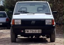
I have been fixing up the front end of the 1000s (it needs a name).
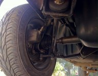
With new lower control arms, new OE dampers and all else reviewed and restored, I now come to the conclusion that the previously repaired front RH wing might only be the tip of the iceberg...
Perhaps the damage is more than skin deep.
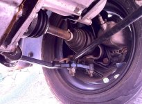
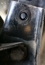
The RH front wheel has a ton of +ve camber, resembling more a classic Fiat rear-engine car, whilst the LH is more or less vertical as should be. I have the feeling that the control arm bush sits crooked in the body bracket.

My options are to push the control arm body bracket into position ( not sure how to do this), or re-adjust the camber with an adjustable bolt (if it exists for a Panda).
The mot is coming up on 26th sept, I don't know if it'll pass like it is, plus I really don't fancy living with as it is it either!!

Anyone have experience of such a problem?

Thanks for your time, here's a photo of the front end...
Cheers!
 

Attachments

  • image.jpg
    image.jpg
    370 KB · Views: 168
I should add that after mounting and testing, the previously straight steering wheel had now moved to the 1 o'clock position... I made no steering adjustments in the strip down. The car still goes bullet straight, as it did previously.

After measuring the distance between the tie-bar (radius rod) front brackets and the control arm brackets there is only a 6mm difference between each side (which can't affect the camber noticeably. Perhaps the bracket is pushed in towards the engine?
I referred to the Haynes for the strip down, found no faults in the bearings or ball joints. The strut top bushes, the struts, track control arm and nuts and bolts were replaced with new.

I'm stumped... :bang:

Here's the underside; the tie-rod bracket is photo top centre, the control arm bracket at right. For orientation purposes, that's the wheel photo left! ;)
 

Attachments

  • image.jpg
    image.jpg
    776.1 KB · Views: 55
wheel camber is not adjustable in panda front susp,if the car body is ok all should be within fiat spec. numbers, but you can adjust it by making a "bean shaped" hole for the upper m10 bolt connecting shock absorber with pressed steel element holding the bearing. look at the photo.4x4 guys use this trick to adjust the camber with lifted suspension. Before making any bean holes, check if the holes for the bolts are 10mm and the bolts are m10, panda 4x2 has m10 bolts and 10mm holes, panda 4x4 has m12 bolts and 12mm holes, if someone used 4x4 m12 pressed steel element and 4x2 m10 bolts there is 2mm play on upper and bottom bolt, and the camber may be random.


Thanks bartpanda for the advice.
I know that I have 10mm bolts and holes, as I just installed new bolts. I am familiar with the bean shaped holes you mention, after a recent rebuild of our subaru's suspension, which has adjustable camber bolts.
If I cannot find the fault this weekend I'll look into fitting the camber bolt as you recommend, thanks!

I have now noticed that I have more steering lock to left than to right, 2 1/8 turns left compared to 1 3/4 turns right.
This is since I re-adjusted the steering wheel after it being 1/8 of a turn to right, after rebuild. Could the new dampers be affecting this I wonder?

Ahh well, some fun for Sunday..
 
Hi.

First observation from your photo is - does the other side have the repair type lower ball joint fitted as well or is it still standard?

Yes, Monroe magic camber bolts are available for pandas.
MC210 but please check as i might mix the number
 
Hello Kolza, I reckon you may be better qualified than I to identify a replacement versus original ball joint, so I'll let you take a look! It's certainly different...

I intend to replace these joints along with the housings at some point as the rubbers on both are a little perished, though the joints are firm with zero play.
How could this affect the geometry so much? Wouldn't an aftermarket joint hold the parts in the same way?

Thanks!
 

Attachments

  • image.jpg
    image.jpg
    958.2 KB · Views: 60
I've just had much closer look on it - it looks like it is not the 'repair' type one - just fresh one.

Keep the investigation, please use attached drawings to confrm that the chassis isn't bend or something.
 

Attachments

  • NADWOZIE WYMIARY - CARROZZERIA - SCHEMA PER IL CONTROLLO FONDO SCOCCA.pdf
    235.2 KB · Views: 79
You'd be surprised how much variation you can get on the camber just through the play between the bolt holes at the bottom of the struts, the ball joint housing bolt holes and the bolts going through them. Try slackening off the 2 bolts that go through the bottom there and rocking the wheel and you'll see what I mean, they're not usually a terribly tight fit. With the bolts slightly loose just rock the assembly back in as far as it will go and hold it while you tighten the bolts back up and you might well get it far enough back into position. If you just let it hang while you tighten the bolts the assembly pushes itself naturally as far out into positive camber as the play on those bolts will allow. If the hub carrier relaxes outward while you're tightening up that will move the strut out slightly, so the steering will toe out that side as the track rod end sits slightly further in in relation to the arm compared to where it was previously so that would knock the steering adjustment off too. It doesn't take big movements to knock these adjustments out.
 
Last edited:
Thanks, that sounds like a sensible place to start. As the bolts are fixed I think I left out the "push-in" to sit the struts in the carriers.
I remember doing so with the subaru.
That'll be the first thing to look at today, before any drilling/bending!
 
Well, I've checked the strut lower bolts, and there is about 1mm of adjustment, which equates to maybe 2mm at the wheel top edge.
The wheel top is still hanging out by about 10-12mm... So I guess I'll be ordering some camber bolts then.

Now I know that aftermarket camber bolts should be ONLY fitted in the lower of the two holes in the carrier / strut on cars fitted with camber bolts as standard ( typically in the upper holes).
Should this rule be followed on our cars too?

What I did notice was that even if the bolt holes allowed more play for the bolt, the strut and the hub carrier are now touching along the top edge of the hub carrier. If I were to oval the top holes, I would not be able to force the carrier further inwards, so perhaps I should work on the lower holes for the camber bolt instead.
 
Thank you all for your advice.
After looking at the options, I got looking into the camber bolts, but I fail to see how a camber bolt could work. These bolts need some meat for the cam to work against, this usually being the cast iron upright which sits clamped in the damper bracket.
The panda has the hub carrier sandwiching the damper instead, and as there is no 'meat' inside the damper bracket, the bolt cam has nothing to push against.

Finally I decided to do it this way:
Jack up the front of the car, level it side to side, and measure the camber angle of each hub.
Then I removed the upper of the two bolts, and forced the hub in towards the strut until I reached a matching camber angle for both sides.
As can be seen, the holes of the hub carrier and the strut are misaligned.

My trusty 10mm round file made good the difference, removing the metal from the strut bolt holes. :devil:

Pinched up good and tight, the wheel sits straight again.
Hopefully having elongated the holes won't be a problem...
Thanks again for the great input!(y)
 

Attachments

  • image.jpg
    image.jpg
    427.7 KB · Views: 39
Back
Top