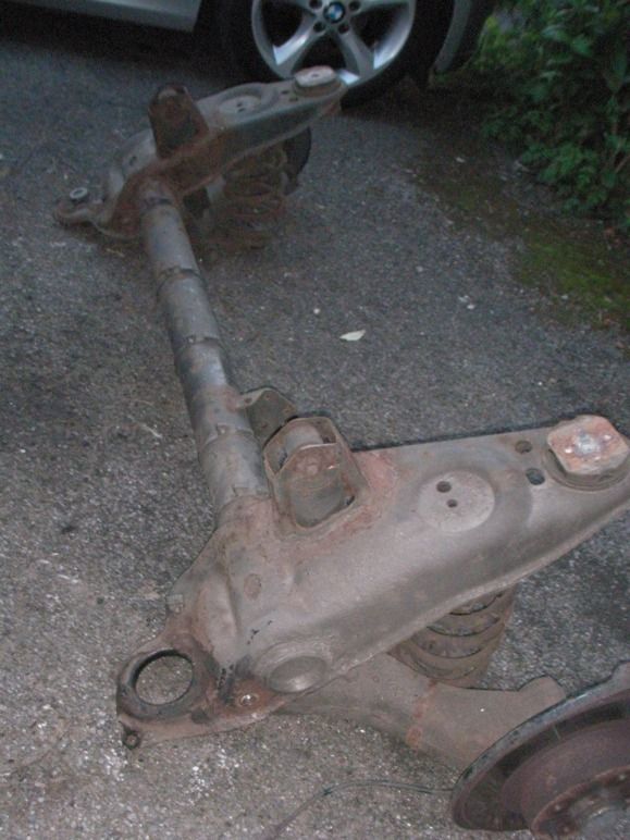
Multipla Trailing Arm Bearing Replacement 110 Elx Jtd 2001 with 127 k miles
I only noticed that I’d got worn bearings by chance, I didn’t have the tyres touching the arches or anything and hadn’t noticed any clunks or any strange handling. Being Mr Stingy, I was just swapping the tyres front to rear after worn track rod ends had allowed the inner edges of the front tyres to scrub slightly.
I just happened to pull on the rear hub and noted an alarming clunk. About 5 mm of play on the arm. The other side wasn’t quite so bad but still showed some movement.
Being new to the site, I looked for solutions but couldn’t find much info. I probably wasn’t searching properly but tales of ‘easier to replace the whole arm’ and ‘difficult
Job - £ 200- £300 per side worried me’. Being a confirmed Citroen addict and having tackled the same job in the past on my beloved CX’s I thought, come on wimp, where’s your moral fibre, they can’t be as bad as all that !
As a (very pleased) newcomer to the Multipla and having already done the clutch, the front roll bar bushes, drop links and usual surprisingly common problems I’m pleased to report they are not too difficult to do. If you have the right tools and moderate mechanic skills it’s worth having a go. Stupidly I didn’t take photos and am writing this after the event but hopefully it will describe how to do it. Maybe catching them early helps, but possibly not.
I did both of mine easily in the day – around 2-3 hours each, but now I know how, could maybe do them a bit quicker.
I had the car on the drive and was able to drop the arms far enough without disconnecting the brake pipes, handbrake cables and ABS and used the old pivot bolts to pull the new bearings, caps, seals and sleeve spacers into the arm. Reassembly was trouble free fortunately.
If you aren’t confident after reading these instructions, then don’t try it, especially if you have no one to turn to if you get stuck. A car with a worn trailing arm bearing is at least mobile and will get to a garage, but a car without the arm is expensive. Post queries if I’ve missed out anything obvious and good luck !
You will need the following :-
Wooden blocks to position on the chassis box sections to spread the load from the axle stands.
Trolley jack and axle stands.
Lump hammer and smaller (joiners type) hammer.
Wheel chocks (bricks).
A drift – luckily I had a round steel bar, 25 mm diameter, about 500 mm long, and with nice, clean cut ends - to knock the old bearing shells out.
24mm, 19mm, (15mm, 13mm) sockets and ring-keys, a ½” ratchet drive with a couple of 4” extensions. Being of slight build, I needed a big torque wrench (about 600 mm long) to undo the big nut and a 21mm spanner.
A flat file and a pair of long nosed pliers.
A small tub of multipurpose grease, copper slip grease and a tin of WD40.
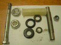
2 No. Bearing kits – mine were £ 40 each, and in stock at the local motor-factors.
Crow/pry bar about 600 mm log.
Washers to help pull the new bearings into the arm – I used about 6 No. M24 steel washers I happened to have, but with care I think you could manage with the old and the new washers and the old end caps.
Cleaning rags and a wire brush.
1. Chock the front wheels with bricks, and loosen the back wheel bolts ½ a turn or so. Why are they always go so tight even when you torque them up so carefully ?
2. Jack up the rear (offending) side of the car and position the axle stand and wooden spreader block on the chassis box sections to take the load. Remember you’ll need to jack the arm back into position, so keep access to that area clear. Lower the body onto the stand and check all is safe, well supported and no ‘wobbles or leans’. Remove the jack and undo the wheel bolts. Remove the wheel and use it as an emergency ‘prop’ under the body, just in case the axle stand fails.
3. Crawl under the car and liberally spray the pivot bolt nut and shock absorber nut with WD40, (and the other side too while you are under there). Allow the oil to soak in for a while (have a coffee), then using the wire brush remove as much mud and rust as you are able from the exposed threads. Spray on more WD40. It looks like from reading old threads that the pivot bolt nut tends to seize and the solution is to cut it off with an abrasive disc. Luckily mine weren’t as bad as that. I used a socket with an actual hexagonal socket rather than the multi-faceted ones which are prone to just strip the corners off the nut. Wire brushing the rust and muck away then spraying with penetrating oil for several days prior to the attempt often helps, and it may be worth trying heating the nut with a blow lamp if you are confident you can avoid melting the handbrake cables, and the fuel tank (fire extinguisher ready).
4. If you are working on the exhaust side (nearside) of the car, you’ll probably need to drop the exhaust slightly to get good access to the area, so lubricate the last pair of rubber support blocks with WD 40, and wiggle them back and forth by hand until they start to slide, adding more WD as needed. After a few seconds you’ll be able to slide them off the steel support pins and lower the exhaust – support it with another stand or something else convenient.
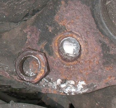
5. Place the 24mm ring key on the outer pivot bolt head with the free end either on the inner wheel arch or the trailing arm depending on which side you are working on, crawl back under the car and using the big torque wrench with 24 mm socket, undo the inner nut from underneath. Mine were very tight, but once moving came off relatively easily. Then undo the shock absorber bottom bolt 19 mm socket with 21 mm spanner on the (square) head to stop it turning. Position the jack under the trailing arm and take the weight. Gently tap out the shock absorber bolt until the absorber hangs free. With the 24 mm ring key, turn the pivot bolt a couple of complete turns to free it from the steel sleeve and then using the smaller hammer tap the pivot bolt outwards from under the car. I might have been lucky, but was then able to pull the bolt out by hand with a bit of wiggling of the trolley jack which was a nice suprise.
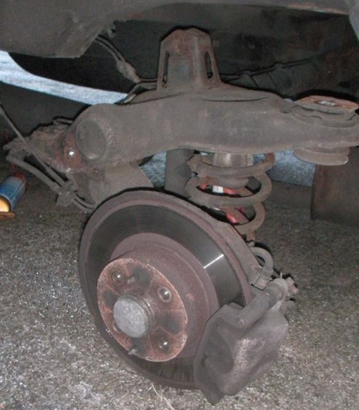
6. Lower the jack slightly and with the pry bar between the trailing arm and the sub frame, gradually work the arm down, lowering the jack, until the arm hangs free. The anti-roll bar is still connected, so stops the assembly from dropping too far, but check that none of the brake pipes, ABS cables or hand brake cable are under any strain, mine had plenty of travel.
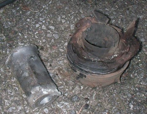
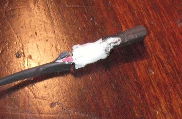
7. Examine the parts in the new bearing kit, in particular the steel sleeve tube so you can recognise it in the old assembly. Spray the exposed outer face of the old bearing seal, clean up with a rag and identify the end of the steel sleeve. Using a drift – I used the old pivot bolt and the lump hammer – carefully positioned against just the sleeve edge/end, a couple of sharp blows were sufficient to drive the inner seal out of the housing and the sleeve could then be withdrawn from under the car. The outer seal then virtually falls out on it’s own or with a small tap with the drift from under the car.
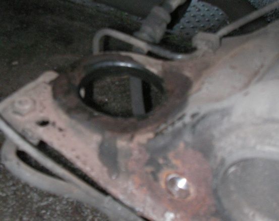
8. All that is left in the arm then are the outer bearing races and the white plastic lubrication sleeve between them. With the flat bladed screwdriver and the small hammer, I gradually worked round the sleeve end, smashing it off, then using the long nosed pliers, push the jaws into the arm, one inside, one outside the sleeve, and then twist the pliers to make it collapse enough to be pulled out of the housing. Clean up the bearing housing with WD40 and a rag and identify the small step between the bearing housing and bearing shell – this is where you’ll need the drift to strike, avoid running your finger over the sharp edges, they could slice a neat cut into your finger end as they did to me. At this stage a black plastic bump-stop cap from inside the lower end of the coil spring popped out – save it to re-fit later.
9. My initial reaction was – ‘S**t – how am I going to drive those shells out of there – this is where I’m going to have to call in help’. Then the ‘Keep calm – this can work out OK’ took hold. So, using the 25mm diam steel drift positioned at say 3 o’ clock on the shell, I took a couple of firm blows with the lump hammer, moved the drift over 9 o’clock and did the same again. Then I ran my finger around the housing (carefully this time) and was delighted to find the shell had moved a couple of mm. Repeating the process a couple more times pushed it right out and there was a pleasing plink as it dropped to the floor. The outer shell came out just as easily too. More WD40 and a rub with rags cleaned the old grease from the housings then I was ready for re-assembly. I always think at this stage, well I’ve done the hard bit now, the rest should be easier – fingers crossed, touch wood and the like.
10. I decided it would be easiest to assemble one end of the new bearing before inserting it in the arm, so after coating the ball race with grease, used the old bolt and washers to pull the bearing onto the steel sleeve, then a similar process to pull the steel and rubber end caps onto the same end of the sleeve. I then coated the outside of the sleeve with grease, and put a big slug into the end of the plastic sleeve. Pushing the sleeves over each other then more or less filled the cavity between the plastic and the steel and I pushed in a bit more grease to be on the sure side.
11. This is where I made my mistake which slowed me down slightly. I decided to insert the new assembly from under the car, with the bolt the wrong way round (nut to the outside). I thought I’d be able to position the outer bearing and end cap more easily. Perhaps it is easier like this, but once the second bearing is pulled into the arm, you can’t withdraw the bolt because the anti-roll bar is in the way. Further swearwords came to mind as I searched for my 15mm and 13mm sockets to loosen the roll bar !
12. Loosening the two 13mm bolts and removing them, but only loosening the 15mm allows the arm to pivot far enough to withdraw the trailing arm bolt, and tightening them back up was easy enough – it probably only delayed me by 10 mins, but was still frustrating.
13. So, insert the (part assembled) bearing and sleeve from the outside of the arm, and with the other greased bearing the right-way round and washers and a nut on the old pivot bolt on the inside, pull them into the arm housings. I then undid the bolt and added the second end cap, and with a bit of fiddly alignment, was able to pull everything together. I kept on tightening and then slackening everything off and checking if the end caps were flush with the inner sleeve before I was happy. It’s surprising how tight this is. Remove the old bolt and washers and give the end caps a final clean up with a rag before putting a dollop of grease inside the steel sleeve ready to lubricate the new bolt.
14. Using the flat file, I gave the inner edges of the sub-frame faces a quick clean up to remove any rust or mud. Maybe a coat of copper grease is a good idea here too.
15. Reposition the jack as close to the pivot end of the trailing arm, there is a slight lump on the underside of the arm which helps, and kept the jack pad away from the hand-brake cable.
16. Checking that nothing in being crushed, (cables, pipes etc) slowly jack the arm back into position, push and pull on the brake drum to make sure the arm is square with the sub-frame housing. If the arm won’t fit – it’s probably because the bearing assembly isn’t fully pulled together – so check and try again.
17. Eventually the arm will reluctantly, although satisfyingly slide into position and you should be able to lever it exactly into alignment with a big screw driver through the bolt hole.
18. Grease the new pivot bolt and insert it from the outside, by hand if possible to avoid damaging the threads, and fit the new washer and nut to the inside and tighten up. I don’t know what the torque setting should be, so I did mine up as far as I could with a standard ½” drive ratchet - perhaps if anyone knows the right settings could you let me/us know. Lower the jack.
19. Check that the arm still pivots freely, and pull and push on the brake drum to check there is no free play anymore.
20. Refit the bump stop cap to the lower end of the arm, levering it into position with the end of the pry bar until it pops back in.
21. For the nearside arm, lift the exhaust back up, lubricate the rubber blocks and slide them back into position
22. Refit the road wheel, tighten the bolts just hand tight and move all your tools from under the car.
23. Reposition the jack, lift the body far enough to remove the axle stand, then gradually lower to the floor.
24. Tighten the wheel bolts to the recommended torque.
25. Congratulate yourself on a job well done and have a refreshing drink before doing the other side !
If this has helped you let me know.
My next job will be to sort a clunking from the nearside strut top end.
I'll try to take photos next time.
Best regards,
Simon
I only noticed that I’d got worn bearings by chance, I didn’t have the tyres touching the arches or anything and hadn’t noticed any clunks or any strange handling. Being Mr Stingy, I was just swapping the tyres front to rear after worn track rod ends had allowed the inner edges of the front tyres to scrub slightly.
I just happened to pull on the rear hub and noted an alarming clunk. About 5 mm of play on the arm. The other side wasn’t quite so bad but still showed some movement.
Being new to the site, I looked for solutions but couldn’t find much info. I probably wasn’t searching properly but tales of ‘easier to replace the whole arm’ and ‘difficult
Job - £ 200- £300 per side worried me’. Being a confirmed Citroen addict and having tackled the same job in the past on my beloved CX’s I thought, come on wimp, where’s your moral fibre, they can’t be as bad as all that !
As a (very pleased) newcomer to the Multipla and having already done the clutch, the front roll bar bushes, drop links and usual surprisingly common problems I’m pleased to report they are not too difficult to do. If you have the right tools and moderate mechanic skills it’s worth having a go. Stupidly I didn’t take photos and am writing this after the event but hopefully it will describe how to do it. Maybe catching them early helps, but possibly not.
I did both of mine easily in the day – around 2-3 hours each, but now I know how, could maybe do them a bit quicker.
I had the car on the drive and was able to drop the arms far enough without disconnecting the brake pipes, handbrake cables and ABS and used the old pivot bolts to pull the new bearings, caps, seals and sleeve spacers into the arm. Reassembly was trouble free fortunately.
If you aren’t confident after reading these instructions, then don’t try it, especially if you have no one to turn to if you get stuck. A car with a worn trailing arm bearing is at least mobile and will get to a garage, but a car without the arm is expensive. Post queries if I’ve missed out anything obvious and good luck !
You will need the following :-
Wooden blocks to position on the chassis box sections to spread the load from the axle stands.
Trolley jack and axle stands.
Lump hammer and smaller (joiners type) hammer.
Wheel chocks (bricks).
A drift – luckily I had a round steel bar, 25 mm diameter, about 500 mm long, and with nice, clean cut ends - to knock the old bearing shells out.
24mm, 19mm, (15mm, 13mm) sockets and ring-keys, a ½” ratchet drive with a couple of 4” extensions. Being of slight build, I needed a big torque wrench (about 600 mm long) to undo the big nut and a 21mm spanner.
A flat file and a pair of long nosed pliers.
A small tub of multipurpose grease, copper slip grease and a tin of WD40.
2 No. Bearing kits – mine were £ 40 each, and in stock at the local motor-factors.
Crow/pry bar about 600 mm log.
Washers to help pull the new bearings into the arm – I used about 6 No. M24 steel washers I happened to have, but with care I think you could manage with the old and the new washers and the old end caps.
Cleaning rags and a wire brush.
1. Chock the front wheels with bricks, and loosen the back wheel bolts ½ a turn or so. Why are they always go so tight even when you torque them up so carefully ?
2. Jack up the rear (offending) side of the car and position the axle stand and wooden spreader block on the chassis box sections to take the load. Remember you’ll need to jack the arm back into position, so keep access to that area clear. Lower the body onto the stand and check all is safe, well supported and no ‘wobbles or leans’. Remove the jack and undo the wheel bolts. Remove the wheel and use it as an emergency ‘prop’ under the body, just in case the axle stand fails.
3. Crawl under the car and liberally spray the pivot bolt nut and shock absorber nut with WD40, (and the other side too while you are under there). Allow the oil to soak in for a while (have a coffee), then using the wire brush remove as much mud and rust as you are able from the exposed threads. Spray on more WD40. It looks like from reading old threads that the pivot bolt nut tends to seize and the solution is to cut it off with an abrasive disc. Luckily mine weren’t as bad as that. I used a socket with an actual hexagonal socket rather than the multi-faceted ones which are prone to just strip the corners off the nut. Wire brushing the rust and muck away then spraying with penetrating oil for several days prior to the attempt often helps, and it may be worth trying heating the nut with a blow lamp if you are confident you can avoid melting the handbrake cables, and the fuel tank (fire extinguisher ready).
4. If you are working on the exhaust side (nearside) of the car, you’ll probably need to drop the exhaust slightly to get good access to the area, so lubricate the last pair of rubber support blocks with WD 40, and wiggle them back and forth by hand until they start to slide, adding more WD as needed. After a few seconds you’ll be able to slide them off the steel support pins and lower the exhaust – support it with another stand or something else convenient.
5. Place the 24mm ring key on the outer pivot bolt head with the free end either on the inner wheel arch or the trailing arm depending on which side you are working on, crawl back under the car and using the big torque wrench with 24 mm socket, undo the inner nut from underneath. Mine were very tight, but once moving came off relatively easily. Then undo the shock absorber bottom bolt 19 mm socket with 21 mm spanner on the (square) head to stop it turning. Position the jack under the trailing arm and take the weight. Gently tap out the shock absorber bolt until the absorber hangs free. With the 24 mm ring key, turn the pivot bolt a couple of complete turns to free it from the steel sleeve and then using the smaller hammer tap the pivot bolt outwards from under the car. I might have been lucky, but was then able to pull the bolt out by hand with a bit of wiggling of the trolley jack which was a nice suprise.
6. Lower the jack slightly and with the pry bar between the trailing arm and the sub frame, gradually work the arm down, lowering the jack, until the arm hangs free. The anti-roll bar is still connected, so stops the assembly from dropping too far, but check that none of the brake pipes, ABS cables or hand brake cable are under any strain, mine had plenty of travel.
7. Examine the parts in the new bearing kit, in particular the steel sleeve tube so you can recognise it in the old assembly. Spray the exposed outer face of the old bearing seal, clean up with a rag and identify the end of the steel sleeve. Using a drift – I used the old pivot bolt and the lump hammer – carefully positioned against just the sleeve edge/end, a couple of sharp blows were sufficient to drive the inner seal out of the housing and the sleeve could then be withdrawn from under the car. The outer seal then virtually falls out on it’s own or with a small tap with the drift from under the car.
8. All that is left in the arm then are the outer bearing races and the white plastic lubrication sleeve between them. With the flat bladed screwdriver and the small hammer, I gradually worked round the sleeve end, smashing it off, then using the long nosed pliers, push the jaws into the arm, one inside, one outside the sleeve, and then twist the pliers to make it collapse enough to be pulled out of the housing. Clean up the bearing housing with WD40 and a rag and identify the small step between the bearing housing and bearing shell – this is where you’ll need the drift to strike, avoid running your finger over the sharp edges, they could slice a neat cut into your finger end as they did to me. At this stage a black plastic bump-stop cap from inside the lower end of the coil spring popped out – save it to re-fit later.
9. My initial reaction was – ‘S**t – how am I going to drive those shells out of there – this is where I’m going to have to call in help’. Then the ‘Keep calm – this can work out OK’ took hold. So, using the 25mm diam steel drift positioned at say 3 o’ clock on the shell, I took a couple of firm blows with the lump hammer, moved the drift over 9 o’clock and did the same again. Then I ran my finger around the housing (carefully this time) and was delighted to find the shell had moved a couple of mm. Repeating the process a couple more times pushed it right out and there was a pleasing plink as it dropped to the floor. The outer shell came out just as easily too. More WD40 and a rub with rags cleaned the old grease from the housings then I was ready for re-assembly. I always think at this stage, well I’ve done the hard bit now, the rest should be easier – fingers crossed, touch wood and the like.
10. I decided it would be easiest to assemble one end of the new bearing before inserting it in the arm, so after coating the ball race with grease, used the old bolt and washers to pull the bearing onto the steel sleeve, then a similar process to pull the steel and rubber end caps onto the same end of the sleeve. I then coated the outside of the sleeve with grease, and put a big slug into the end of the plastic sleeve. Pushing the sleeves over each other then more or less filled the cavity between the plastic and the steel and I pushed in a bit more grease to be on the sure side.
11. This is where I made my mistake which slowed me down slightly. I decided to insert the new assembly from under the car, with the bolt the wrong way round (nut to the outside). I thought I’d be able to position the outer bearing and end cap more easily. Perhaps it is easier like this, but once the second bearing is pulled into the arm, you can’t withdraw the bolt because the anti-roll bar is in the way. Further swearwords came to mind as I searched for my 15mm and 13mm sockets to loosen the roll bar !
12. Loosening the two 13mm bolts and removing them, but only loosening the 15mm allows the arm to pivot far enough to withdraw the trailing arm bolt, and tightening them back up was easy enough – it probably only delayed me by 10 mins, but was still frustrating.
13. So, insert the (part assembled) bearing and sleeve from the outside of the arm, and with the other greased bearing the right-way round and washers and a nut on the old pivot bolt on the inside, pull them into the arm housings. I then undid the bolt and added the second end cap, and with a bit of fiddly alignment, was able to pull everything together. I kept on tightening and then slackening everything off and checking if the end caps were flush with the inner sleeve before I was happy. It’s surprising how tight this is. Remove the old bolt and washers and give the end caps a final clean up with a rag before putting a dollop of grease inside the steel sleeve ready to lubricate the new bolt.
14. Using the flat file, I gave the inner edges of the sub-frame faces a quick clean up to remove any rust or mud. Maybe a coat of copper grease is a good idea here too.
15. Reposition the jack as close to the pivot end of the trailing arm, there is a slight lump on the underside of the arm which helps, and kept the jack pad away from the hand-brake cable.
16. Checking that nothing in being crushed, (cables, pipes etc) slowly jack the arm back into position, push and pull on the brake drum to make sure the arm is square with the sub-frame housing. If the arm won’t fit – it’s probably because the bearing assembly isn’t fully pulled together – so check and try again.
17. Eventually the arm will reluctantly, although satisfyingly slide into position and you should be able to lever it exactly into alignment with a big screw driver through the bolt hole.
18. Grease the new pivot bolt and insert it from the outside, by hand if possible to avoid damaging the threads, and fit the new washer and nut to the inside and tighten up. I don’t know what the torque setting should be, so I did mine up as far as I could with a standard ½” drive ratchet - perhaps if anyone knows the right settings could you let me/us know. Lower the jack.
19. Check that the arm still pivots freely, and pull and push on the brake drum to check there is no free play anymore.
20. Refit the bump stop cap to the lower end of the arm, levering it into position with the end of the pry bar until it pops back in.
21. For the nearside arm, lift the exhaust back up, lubricate the rubber blocks and slide them back into position
22. Refit the road wheel, tighten the bolts just hand tight and move all your tools from under the car.
23. Reposition the jack, lift the body far enough to remove the axle stand, then gradually lower to the floor.
24. Tighten the wheel bolts to the recommended torque.
25. Congratulate yourself on a job well done and have a refreshing drink before doing the other side !
If this has helped you let me know.
My next job will be to sort a clunking from the nearside strut top end.
I'll try to take photos next time.
Best regards,
Simon