Technical 2010 x250, 160 3.0 immobiliser light on and non start

Currently reading:
Technical 2010 x250, 160 3.0 immobiliser light on and non start

19shimmy56

New member
Joined
Apr 27, 2014
Messages
13
Points
5
Location
York
Hi everybody, my ducato will not start. it cranks over fine but will not fire. The dash is displaying the padlock sign, or (Vehicle protection system failure), but its not displaying the engine management light!.I also get a msgs saying Airbag failure, Hill assist fail, ASR fail,
This leads me to think fuses or relays or bad connection.
So far:-
Disconnected battery to try and clear memory.
Removed n/s headlamp to check for chaffing wires etc.
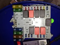
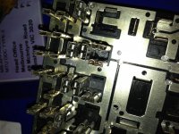
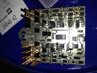
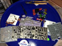
Unplugged all connectors and removed engine bay fuse box, all connections are good and no verdigris on pins
I have checked all fuses in both fuse boards, but I cannot identify the relays.
I have tried to download the free workshop manual to my computer but it wont have it, probably to old and short of space.
Would anybody please have a photo or diagram listing the relays so I can identify which is which.
I`m working blind now and getting very frustrated, as a self employed courier (retired mechanic) I obviously want to try and resolve as much as I possibly can and get back on the road.
Any thoughts or ideas greatly welcomed and appreciated.
Oh by the way have had it plugged into a Bosch ktm code reader and no faults flagged, although this could be linked to lack of management light.:bang:
 
I had some strange messages, take off 2 x main cables on starter motor & clean, I think 13mm nut. worth a try, fixed mine & I found it by accident when I removed starter motor to check it everything was good when I put it back.
 
Hi Kahcorp, many thanks for your suggestion, I have tried as you suggested but still no further forward.
Ideally I would like a diagram of the relays on the fuse boards, if anybody can help.
 
Fuse box diagrams and fuse designations are show from page 178 of the owner's handbook. You can download a copy here https://www.fiatforum.com/downloads.php?do=download&downloadid=135 if you don't have one.

There is no single diagram of the relays or their functions. Instead, they are shown in numerous individual wiring diagrams in the eLEARN workshop manual.

The padlock symbol usually means that the immobiliser chip in the key has not been recognised by the body computer. Assume you've tried both keys, the code transmitted by each one is different.
.
 
Hi Davren, many thanks for your reply. Yes I have the handbook and know what you mean re the relays. I cant seem to download the manual, although my wife is having a go on her laptop as we speak.
Yes I have tried both keys but to no avail. It seems odd that there isnt a management light on the dash which says to me perhaps a power feed or an earth missing, hence all the extra msgs on the dash. Somebody also said to me that if it was coded immobiliser at fault then it wouldnt even crank, which it does.
Very confused and frustrated of York
 
Somebody also said to me that if it was coded immobiliser at fault then it wouldnt even crank, which it does.

I'm not that familiar with the Ducato, but I was under the impression that most cars and light commercial vehicles equipped with a chipped immobiliser key would operate the starter motor if the key signal was absent. I believe the immobiliser only inhibits the engine management ECU and therefore the fuel pump. I've used this for at least 20 years so I can use the starter motor as a substitute high rate discharge tester for testing batteries. Almost invariably, wrapping the key handle with thick aluminium foil to stop the signal getting to the ignition switch receiver aerial, has operated just the starter motor.

With so many other failures showing, I'm surprised you're not getting any fault codes. Is the Bosch code reader you're using capable of reading Fiat manufacturer specific body (B), chassis (C) and communication (U) codes?

Just tested the Ducato manual download, it's works perfectly. The individual files won't work separately, you need to download all 7 parts into the same folder, then point WinRAR (or similar) at part 1. That will unzip all 7 parts into one ISO image file. Then use ImgBurn (or similar) to create a CD from the image file.
.
 
Hi Davren, thank you for your input. Youre probably right re the cranking, but I am working blind as we cannot get the workshop manual to open. We have tried to copy to cd but my wifes computer which has Win 10 says there is a problem with the CDr format. Any Ideas?
I think the lack of fault codes is because there isnt a switched live to the ecu, hence no MIL light.I have removed and tested every single relay and fuse and havent found a problem so far.
Next step now is to take off the st/column shrouds and start testing from the ignition switch forward, but again progress is slow as I dont have a wiring diagram.
I shall soldier on.!!

have you attempted to clear the ECU's of error codes.. it could be something daft blocking it..

Charlie
 
This is the starting and charging schematic. I will try and get details of the immobiliser.
 

Attachments

  • FIAT%20X250%20Starter,%20Alternator[1].pdf
    156.5 KB · Views: 181
Last edited:
Schematic diagram off the code system.
Let me know if you want an explanation:
B002 Junction unit under dash
B099 Maxi fuse on batter
C022 centre dashboard earth
E050 instrument panel
H001 Ignition switch
M001 Body computer
M010 ECU
P091 Aerial for code
 

Attachments

  • Code.jpg
    Code.jpg
    122.6 KB · Views: 278
we cannot get the workshop manual to open. We have tried to copy to cd but my wifes computer which has Win 10 says there is a problem with the CDr format. Any Ideas?

You don't need to copy anything to CD..... Once you've used WinRAR to unzip and combine the 7 files into one ISO image file, you create a CD from the ISO image file using a program such as ImgBurn.

Creating a CD from an image file, and copying a file to a CD, are completely different procedures.
.
 
Schematic diagram off the code system.
Let me know if you want an explanation:
B002 Junction unit under dash
B099 Maxi fuse on batter
C022 centre dashboard earth
E050 instrument panel
H001 Ignition switch
M001 Body computer
M010 ECU
P091 Aerial for code
Hi ray c, thank you very much for all the information, I have downloaded and printed it all off. I think I will be ok re explaining, Im pretty good with schematics. This will help a lot as i grit my teeth and start on it again in the morning. Thank you all again for your help. Steve
 
You don't need to copy anything to CD..... Once you've used WinRAR to unzip and combine the 7 files into one ISO image file, you create a CD from the ISO image file using a program such as ImgBurn.

Creating a CD from an image file, and copying a file to a CD, are completely different procedures.
.
Hi Davren, sorry if I`m being a bit blonde about all this, but my head is spinning with wiring looms, relays fuses etc. I will try again as you suggest. Many thanks. Steve
 
Hell everybody. here is an update to the above problem.
Yesterday myself and a long time friend from my motortrade days finally fathomed out the problem and she now starts up......Yeahhh.
So the engine bay fuse box that sits alongside the ecu, in there 20amp fuse no 22 is labelled Ei primary services in the owners handbook. The fuse tests out perfectly, and it has a 12v ignition switched feed in, (Brown wire), but there isnt anything coming out (Grey wire)???. I didnt want to dismantle the entire fuse box , so ran a test feed 12volts to the grey and everything started working, the padlock light went out, the MIL light came on and we had 12v feed in to the ecu.
Turned the key to crank it over and away she went. I have installed a temporary 12v switched feed to get me up and running whilst I get to the bottom of the problem.
Now does anybody have a diagram of the internals of the engine bay fuse box please?
Also a very big thank you to all who have contributed and assisted with schematics etc, and to the pints of Black Sheep consumed while chewing over the problem in the pub.!!
I must praise the honesty of the folk at Autoecu in Leicester who I had a long chat with, he could quite easily have told me the immobiliser unit wanted testing or changing or some thing and relieved me of £££££`s instead he steered me to different thinking.
Thanks again to all.(y)
 
Had a very similar problem with my 2008 motorhome it turned out to be the multi pin plug at fault with the pin out of fusebox being live but the crimped wire on the female side being broken so no live going to the grey wire.
Well done in finding it fait garage would just keep putting bits on till they sorted it!!!!!
Regard Lexion.
 
Now does anybody have a diagram of the internals of the engine bay fuse box please?

Other than the various individual wiring diagrams of circuits that are protected by, or pass through, the fuse box, there are no other diagrams available.

If the Ducato fuse box is the standard pattern used in most current Fiats, it will consist of several metal plates that connect or insulate the various circuits, and contain fuse sockets connected to the appropriate plate.

Pictures below are of a Fiat Stilo fuse box. If the overall design is similar to yours, it could show you what to expect if you dismantle yours. Of course, the plates and connections are likely to be different to your Ducato one.

The pictures are from this Stilo guide: https://www.fiatforum.com/stilo-guides/313986-how-clean-dry-out-fuse-box-near-battery.html
.
 

Attachments

  • Stilo Fuse Box 1.jpg
    Stilo Fuse Box 1.jpg
    2 MB · Views: 80
  • Stilo Fuse Box 2.jpg
    Stilo Fuse Box 2.jpg
    2.4 MB · Views: 81
  • Stilo Fuse Box 3.jpg
    Stilo Fuse Box 3.jpg
    2 MB · Views: 75
  • Stilo Fuse Box 4.jpg
    Stilo Fuse Box 4.jpg
    2 MB · Views: 77
Other than the various individual wiring diagrams of circuits that are protected by, or pass through, the fuse box, there are no other diagrams available.

If the Ducato fuse box is the standard pattern used in most current Fiats, it will consist of several metal plates that connect or insulate the various circuits, and contain fuse sockets connected to the appropriate plate.

Pictures below are of a Fiat Stilo fuse box. If the overall design is similar to yours, it could show you what to expect if you dismantle yours. Of course, the plates and connections are likely to be different to your Ducato one.

The pictures are from this Stilo guide: https://www.fiatforum.com/stilo-guides/313986-how-clean-dry-out-fuse-box-near-battery.html
.
Hi Davren, sorry for delay replying, have been away on work. Thank you for the pictures that answers a lot and it is as I thought.
I realised the other day that I still have the old loom from my 07 Ducato in a box in my workshop, so I will dissect into that and find the absolute path of these wires.
I will post photos as and when I manage to do this.
Once again thank you to all for your input and advice, pics etc. Steve
 
Back
Top