Technical how to find the lambda input (iaw 18fd.5z)

Currently reading:
Technical how to find the lambda input (iaw 18fd.5z)

Joined
Jun 12, 2011
Messages
2,288
Points
452
Location
Great Yarmouth
im hoping someone on here will know the answer to my question

basically ive just put a new wideband in the cinq (innovatte motorsport lc-02) and i think.... the original fiat lambda has eaten itself, lumpy idle, high afr on idle, stinks when blipping the throttle and the emissions were a nightmare to get through at mot time....

ive seen it done before and know its possible to connect the narrow band out put signal wire from the controller to the ecu to give it the reading that the standard lambda would anyway, im not trying to be tight with this id just rather use the wideband to its potential :D

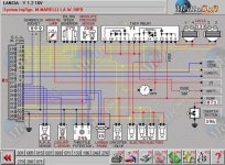
so is there anyone out there that could give me the correct pinout for the lambda signal wire to the iaw 18fd (mk1 p85 1.2 16v mpi)
i have found a pinout for this ecu but it seems to have two inputs an earth and a line out to the inertia switch :confused:

im looking at pin 12 and pin 29... i assume one will be a +ve and one will be a -ve??
do i need to connect into one or both??

cheers in advance and as always much appreciated (y)

Lee


EDIT>>> the lambda signal is to pin 29, by process of elimination :p one is grrey he other is black :p so ive unplugged the oem lambda and plugged the no.2 output from the wideband controller to pin 29 and it now runs a dream :D

hope this info helps someone along the way

lee
 

Attachments

  • p34.jpg
    p34.jpg
    364.8 KB · Views: 2,549
Last edited:
Wow i'd forgotten how bad that wiring diamgram actually is. After seeing it used by Todger & Whitz for slugworths 16v swap i decided to try and find any of the proper diagrams that are in the back of the haynes book. Most haynes copies i found didnt have the wiring section but after an evening or two of searching i have copies of all the Mk1 wiring diagrams. I've cropped it and uploaded a very large copy and even a seperate one the key and added the colour codes too :)
I do have a more complete list of the all component numbers but its four pages long, so below is a smaller version.

This is the 1997 diagram, ill upload all ive got and send you the rest if you want?

Lambda is item 125 (top in the middle)
I'll go left to right with the wires (as seen on the diagram) and number them 1 to 4.

No. 1 MB - Brown / white. This joins with two other wires; one brown/white, leading up to item 124 'multiple relay'. The other they join with; green/white and leads into item 33 'front/fuel injection cables'. On another key ive got this is listed as 'front wiring connection'.

No. 2 NV - Black / green. Leads to item 130 'Earth on engine'. Again according to the other key.

No. 3 G - Yellow. Into ecu pin 29

No. 4 N - Black. Into ecu pin 12

however the wires into the ecu have a dotted box around them and at the pin end their colour codes are reversed. Personally im still none the wiser about which could be which but hopefully the diagram will allow others to figure it out. Perhaps they could be swapped round and it not matter? Are the colour codes closer to the sensor,the colour of the wires near the sensor and the colours in the dotted box by the ecu, are they the colours of the wire from the ecu to the lambda connector?

Bit of discussion from pistonheads about lambda wiring and testing suspected faulty sensors.
http://bit.ly/1M9T77s

Written all the above out for others that may have any difficulty with this in the future and actually get a decent copy of the 18FD Wiring Diagram online.
(plus if anyone searches the above phrase, google should index it now, they'll easily find it)

Click the images to see a larger version


Hope some of that was of use to you Lee, sorry i couldnt be of more help

Pirus
 
Found another file ive got on my PC of the pin outs of the 18fd from autodata. This time as three seperate large images. It was a PDF file but converted it to images, as that's what this forum allows and if i put it on a different site to host, who knows how long before it got taken down.


So according to this info:
Pin 12 - engine idling. Switched earth.
Pin 29 - engine hot. Input signal. Voltage values between 0.1-1v.

Clearer now :)
 
Last edited:
Now it is too late, nevertheless. Pin 12 is the lambda -/ground, pin 29 is the +/signal, this was to be found in the description of my converter plug from 4AF to 18F in my thread ;)

Which AFR controller are you using for the narrow band emulation? I wonder how is this going to work for you. I use Zeitronix and my 18F likes it, but I think the 4AF is not that happy about it, but I cannot really pin it down as there are other problems with my 4AF installation still.

well i wired it into pin 29 in the end, im using a innovate motorsport lc-02 for the emulator and it doesnt work lol.... i disconnected the standard fiat lambda and ran a wire from the wide band controller to the ecu (pin 29)... it was fine to begin with but seems when it was hot, i.e been sat at idle for a while, it drove like poo... popping and spluttering anything under 4k rpm in every gear, so i reverted it back to the original setup with a spare lambda that i had laying around, i think i need to plug the wideband controller in and tune the settings as to what voltage it sends at what point...

il give it another try in a few days.. but for now it can just stay as it was, i needed the car today and wasnt happy with it

cheers
lee
 
woj's first law of electricity says "each electrical component needs at least two wires connected to somewhat function." :D Realising this some time in the past helped me a lot with many electrical issues ;) What I mean in this particular case is that I would strongly recommend connecting the (sensor) ground from LC-2 to ECU pin 12. Configuring LC-2 should of course be considered too, but I do not know much about LC-2 to give you advice. But it should have some sort of a preset for narrow band emulation.

But overall this might be an issue with 18FD - by now I have the lowest possible opinion about this ECU and it might be that it will simply refuse to work with emulated lambda signal.

I agree.. the ecu is utter pants.... I plan on going to the det3 soon so probably wont even bother trying again... ive never had either the 1.2 or the 1.4 16v engines running perfectly on this ecu, always had problems with missfires lower down in the rev range and to be honest if it wasnt for the funds id most likely gone for megasquirt already... however.. the more I read on youre turbo build thread the more I want one of youre ecus for my 8v turbo build :p

may fire you a pm sooon (y)
I thought you was going MegaSquirt?
 
I thought you was going MegaSquirt?

I wil be eventually :p ... plans are either to get the det3 running on the 16v (as it doesnt matter if it goes pop) and then when ive mastered the art of the mapping ill look into getting the ms2 or alternative management, however i do want the toys i.e the launch control. Solinoid boost control, switchable maps ect...
 
Back
Top