

You are using an out of date browser. It may not display this or other websites correctly.
You should upgrade or use an alternative browser.
You should upgrade or use an alternative browser.
Technical 6F/16F Cinque/Sei ECU Reader Project
- Thread starter Jamieboy
- Start date
Currently reading:
Technical 6F/16F Cinque/Sei ECU Reader Project
CinqSporting97
New member
Thanks for that. I had a look and his interface seems to communicate using ISO9414, I don't think the 16F uses this protocol.
Do you know anyone who has been successful in interfacing with the Cinq using home made kit?
Do you know anyone who has been successful in interfacing with the Cinq using home made kit?
As i said, the ECU is similar and I asked him about if it could be adapted to work on a cento and he said yes.
I gave up looking at the idea because my car now runs a megasquirt ECU.
I gave up looking at the idea because my car now runs a megasquirt ECU.
Serial Level to TTL Conversion
Ive seen them before using an optoisolator between the MAX232 and the EEC. I recall the supply was taken from another source (eg the car battery with suitable voltage regulation), and the entire system was referenced to the same earth.
The L line is Tx and K line is Rx. Section 3 of the document details how to do it....would the English conversion help? It says something about ISO4 standard, but Im not sure on the meaning / implicatons of that that.
Id be VERY interested in seeing your code - the entire reason I never continued this was because Im really not a software engineer....
Last edited:
CinqSporting97
New member
...funny you should say that, I am (a software engineer that is). The software isn't really a problem, I have built a simple PIC system which will listen for the ISO code @ 1200 baud, reply with the initialisation sequence of 0xff 0xaa 0xcc @ 1200 baud and then switch to 7812.5 baud (produced exactly in software). From there it queries the RAM and EEPROM error code registers and then flashes an LED indicating the number of errors found.
This is a simple test rig, once this is up and running I was intending to write a PC application that would display the detailed error information and realtime sensor values.
I am familiar with the MAX232 and I have used it to interface PICs to the serial ports of computers. I prototyped a simple MAX232 setup and connected it to the K line of my ECU, there was no discernible change in the output when the ignition was turned on.
The ISO 4 standard (in terms of electronic communications standards) means nothing to me. Wikipedia defines it as "ISO 4 is an international standard which defines a uniform system for the abbreviation of journal titles", I don't think that's what Fiat use") .
.
Do you have any sources that confirm if the ECU outputs 0-12V on the K line or TTL 0-5V?
Update:
I suspected there may be quite a bit of stray capacitance between GND and my K line, because after switching off the ignition the output seemed to drop to zero in a nice long curve. If there was a big capacitance across GND and K the ECU would have a hard time pulling the output down to zero when it is outputting the ISO code.
So I removed the ECU from the car to eliminate wiring, sensors, the radio, etc and powered it up on the table... Still getting the same output. :bang:. Is the ECU faulty???
I will have access to an oscilloscope at the weekend and I will try to get a proper view of what the ECU is putting out on the K line.
Can anyone else get an oscilloscope waveform from the K line of a cinq, so I can compare?
If not even a voltage reading would be better than nothing.
This is a simple test rig, once this is up and running I was intending to write a PC application that would display the detailed error information and realtime sensor values.
I am familiar with the MAX232 and I have used it to interface PICs to the serial ports of computers. I prototyped a simple MAX232 setup and connected it to the K line of my ECU, there was no discernible change in the output when the ignition was turned on.
The ISO 4 standard (in terms of electronic communications standards) means nothing to me. Wikipedia defines it as "ISO 4 is an international standard which defines a uniform system for the abbreviation of journal titles", I don't think that's what Fiat use
.Do you have any sources that confirm if the ECU outputs 0-12V on the K line or TTL 0-5V?
Update:
I suspected there may be quite a bit of stray capacitance between GND and my K line, because after switching off the ignition the output seemed to drop to zero in a nice long curve. If there was a big capacitance across GND and K the ECU would have a hard time pulling the output down to zero when it is outputting the ISO code.
So I removed the ECU from the car to eliminate wiring, sensors, the radio, etc and powered it up on the table... Still getting the same output. :bang:. Is the ECU faulty???
I will have access to an oscilloscope at the weekend and I will try to get a proper view of what the ECU is putting out on the K line.
Can anyone else get an oscilloscope waveform from the K line of a cinq, so I can compare?
If not even a voltage reading would be better than nothing.
Last edited:
Hi. I'm really quite interested in this also, although my knowledge is pretty limited but I'm keen to give most things a try. I have the circuit diagram from the original diagnostic link designed by barnacle on the fccuk thread, I built it for my old coupe but never got round to using it before the coupe was written off. It's an older version using a max202 chip.
I don't have access to an oscilloscope but will try and check the k-line voltage on my cinq later.
Having read through the more recent work of barncle on the coupe pages, it would be very impressive if someone could produce a product similar in capabilities to his "widget" that displays live ecu readings on a lcd, and also allows data logging to pc and error code reading.
I've attached the converter diagram, if it's any use.
Cheers
Pete
Attachments
CinqSporting97
New member
Thanks peteu,
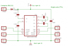
The circuit diagram you have attached does seem to confirm that the ECU outputs TTL levels to the interface. If this is the case then my ECU is doing something strange.
I have definitely obtained a reading of just over 10volts repeatedly, between pin 3 (K) and GND.
I am not sure that the circuit diagram attached though will work as expected, but anyone please feel free to correct me if I am wrong.
AFAIK, the K line is the data output from the ECU - the L line in the data input to the ECU.
The pins on the MAX202 and MAX232, etc are labelled from the perspective of the TTL (the ECU) side of the chip . i.e. T1IN is the TTL input (going towards the MAX chip) for transmission channel 1. T1OUT is the RS232 output of transmission channel 1. R1IN is the RS232 input of reception channel 1 and R1OUT is the TTL output (going to the ECU) of reception channel 1.
That is, whenever the ECU transmits on the K line, the K line is connected to T1IN, the MAX chip converts this to RS232, outputs it on T1OUT and T1OUT is connected to the receive pin on the computer serial port.
In the attached diagram the L line is connected to T2IN, meaning that the ECU should be transmitting on the L line. The K line is connected to R2OUT, indicating that the ECU will receive on the K line.
It is my opinion that these two lines have been mixed up and K should go to T2IN and L to R2OUT. The RS232 side of things looks fine.
Can someone confirm my assumptions about the direction of the K and L lines and the pin assignments for the MAX202/232?
peteu, it would be great if you could check your K line voltage. However, if the output is indeed TTL it would be quite possible to get a reading of 0v with the ignition on, when the K line is idling (not outputing the ISO code).
What I mean to say is you might miss the voltage flickering up to 5V as the ECU outputs the ISO code and then falls back to zero. Make sure you can see the multimeter clearly whenever you turn on the ignition.
If I can get my communications issues cleared up I would be more than happy to start developing a device like barnacle's widget.
- Joined
- Jun 29, 2006
- Messages
- 792
- Points
- 127
I have built several interfaces and can tell you guys that its best to use the MAX232 rather than the opto method, because you need to write s/w to switch control lines for -12v etc.
The output from MAX232 is in the correct phase for driving the immo, but the logic is 0 to 12v so you need to level shift it. IIRC the o/p from ecu is open collect so if you use a 5k pull up it would read +12v on idle and zero v on signal. I dont know the level switching voltage, but obviously if its above 5v operating without a level shifter would give problems.
Simplist solution is to use a non_inverting chip from interface tx pulled up to batt volts. On the rx from ecu use a serial resistor 5k to ttl input to MAx232 and clamp the input pin with a 5v zener.
If I could put a picture on here I could make it more plain.
CinqSporting97
New member
reddy4bed - Thanks for that. I see what you're getting at. Simply shift up the ttl output from the MAX232 to 0-12V and clamp the K line output from the ECU so that it does not exceed 5V. Have you ever interface to the 16F specifically?
It was my thinking too that the K line would be open collector and drive to GND when active. However I am getting a voltage of 10v across K - GND with the ignition on and no external pull up.
peteu is going to check his K line voltage, can anyone else give it a try so I can determine if it's my ECU that's faulty or it is expected behaviour.
- Joined
- Jun 29, 2006
- Messages
- 792
- Points
- 127
CinqSporting97
New member
That interface looks good. I can't see any problem with it working providing the ECU output is open collector and the input expects 0-12V.
If someone can tell me for sure that this is how the 16F behaves I would love to know rather than flog a dead horse / ECU.
I think there is only so far you can go though if you were to connect this to a computer serial port directly.
The computer's UART will be able to receive the ISO code @ 1200 baud (a standard PC speed) and send out the initialization sequence, but once the ECU switches to 7812.5 baud, you will not be able to set a standard serial port to that speed in order to communicate with it.
My intention is to connect a PIC to the ECU and handle the initialization and speed changes, using "bit-banging" software routines to achieve 7812.5 baud. (This part I have already done)
Then use the PICs inbuilt UART to connect to a PC at something like 9600 baud and act as a middle man between the two.
If someone can tell me for sure that this is how the 16F behaves I would love to know rather than flog a dead horse / ECU
.I think there is only so far you can go though if you were to connect this to a computer serial port directly.
The computer's UART will be able to receive the ISO code @ 1200 baud (a standard PC speed) and send out the initialization sequence, but once the ECU switches to 7812.5 baud, you will not be able to set a standard serial port to that speed in order to communicate with it.
My intention is to connect a PIC to the ECU and handle the initialization and speed changes, using "bit-banging" software routines to achieve 7812.5 baud. (This part I have already done)
Then use the PICs inbuilt UART to connect to a PC at something like 9600 baud and act as a middle man between the two.
- Joined
- Jun 29, 2006
- Messages
- 792
- Points
- 127
Ive read lots of 16F and this i/f always works.
You do not need to bother with PIC interface etc, you can set the port baud rate to almost anything. I've sent a working prog (sorry its DOS only) with the assembler file so you can write a better one! the method to change baud rate is in there, also look up the serial port chip on web.
You do not need to bother with PIC interface etc, you can set the port baud rate to almost anything. I've sent a working prog (sorry its DOS only) with the assembler file so you can write a better one! the method to change baud rate is in there, also look up the serial port chip on web.
Attachments
CinqSporting97
New member
It is encouraging that you have interfaced with 16Fs in the past. You are quite right, the assembly code you posted sets up the serial port to 7680 baud after the initialization sequence. That's about 98% accurate, which isn't bad. The reason I was going for a PIC solution was that I didn't know how tolerant the ECU was to inaccurate baud rates.
The PC route would be good for laptop based diagnostics, while the PIC would be suitable for a handheld scanner / real time sensor value display, etc.
Once I get the oscilloscope on the line I will now better what is going on.
The PC route would be good for laptop based diagnostics, while the PIC would be suitable for a handheld scanner / real time sensor value display, etc.
Once I get the oscilloscope on the line I will now better what is going on.
EI4GGB
Member
howye lads..
another interesting discussion on diagnostics. I've been looking to mess with FIAT ECU's and diagnostics for a while now too. If you were looking for a handy interface to avoid having to mess with baud rates, its possible the OE2700 universal tester chip for the mobyDic interface might do the job. its made by a guy called bulent ozen, in turkey, at www.ozenelektronic.com.
It would let one concentrate on the higher level software.
I have the original mobyDic interface, for EOBD. which seems to connect to most cars I've tried it with, except a few petrol FIATS.
he also has a FIAT tester chip which plugs into the original mobyDic interface and works with his own software. It seems to do airbags and other stuff as well, which would be nice.. Its price has come down a bit, and I'd gladly buy one to test if the guy would just answer an email !. he has some useful info there as well.
as for a normal serial interface I'm pretty sure that the standard 12 volt K-line interface is what the marelli ECU's use.
Cinqsporting97, you say you would use bit banging for the serial, but would it not be easier to set the PIC uart to the required baud rate ?. Of course it gets tricky with crystal choice when you are dealing with funny baud rates.
Asteris, you could try the trial download of WINOLS to try and discover the map locations. It tries to identify maps, by looking for patterns. works fairly well too, although I only tried it on JTD and other diesel maps.
Owen.
Hi Cinqsporting97, sorry for the delay in replying, had a busy day yesterday.
I dont know much about the cinq ecu, and the rest of this is from what I can remember from 5 years ago with the coupe, but the coupe ecu definately outputs ttl levels. I'd imagine the cinq is the same, but then again it is a fiat!
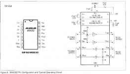
Hmm yes you are right, looking at it the K and L lines are the wrong way round on the diagram above, the attached diagram here is from the max202 spec sheet and shows the chip pin labelling.
I'll try and get out this afternoon whilst it's still light and have a go measuring the k-line voltage
Thanks peteu,
The circuit diagram you have attached does seem to confirm that the ECU outputs TTL levels to the interface. If this is the case then my ECU is doing something strange.
I have definitely obtained a reading of just over 10volts repeatedly, between pin 3 (K) and GND.
I dont know much about the cinq ecu, and the rest of this is from what I can remember from 5 years ago with the coupe, but the coupe ecu definately outputs ttl levels. I'd imagine the cinq is the same, but then again it is a fiat!
I am not sure that the circuit diagram attached though will work as expected, but anyone please feel free to correct me if I am wrong.
AFAIK, the K line is the data output from the ECU - the L line in the data input to the ECU.
The pins on the MAX202 and MAX232, etc are labelled from the perspective of the TTL (the ECU) side of the chip . i.e. T1IN is the TTL input (going towards the MAX chip) for transmission channel 1. T1OUT is the RS232 output of transmission channel 1. R1IN is the RS232 input of reception channel 1 and R1OUT is the TTL output (going to the ECU) of reception channel 1.
That is, whenever the ECU transmits on the K line, the K line is connected to T1IN, the MAX chip converts this to RS232, outputs it on T1OUT and T1OUT is connected to the receive pin on the computer serial port.
In the attached diagram the L line is connected to T2IN, meaning that the ECU should be transmitting on the L line. The K line is connected to R2OUT, indicating that the ECU will receive on the K line.
It is my opinion that these two lines have been mixed up and K should go to T2IN and L to R2OUT. The RS232 side of things looks fine.
Can someone confirm my assumptions about the direction of the K and L lines and the pin assignments for the MAX202/232?
Hmm yes you are right, looking at it the K and L lines are the wrong way round on the diagram above, the attached diagram here is from the max202 spec sheet and shows the chip pin labelling.
peteu, it would be great if you could check your K line voltage. However, if the output is indeed TTL it would be quite possible to get a reading of 0v with the ignition on, when the K line is idling (not outputing the ISO code).
What I mean to say is you might miss the voltage flickering up to 5V as the ECU outputs the ISO code and then falls back to zero. Make sure you can see the multimeter clearly whenever you turn on the ignition.
If I can get my communications issues cleared up I would be more than happy to start developing a device like barnacle's widget.
I'll try and get out this afternoon whilst it's still light and have a go measuring the k-line voltage
Attachments
- Joined
- Jun 29, 2006
- Messages
- 792
- Points
- 127
If you look at the max202 info you will see that there is an inverted output,
ie when the rs232 line is idle (-12v) the ttl o/p is idle at +5v. Likewise when
the ecu is at idle its tx line will be high but at a shifted level, believe me I've done loads of testing on them. If the crossover point at the i/p to ecu is 7v then ttl logic is not going to work without shifting.
ie when the rs232 line is idle (-12v) the ttl o/p is idle at +5v. Likewise when
the ecu is at idle its tx line will be high but at a shifted level, believe me I've done loads of testing on them. If the crossover point at the i/p to ecu is 7v then ttl logic is not going to work without shifting.
CinqSporting97
New member
I had a chance to connect my 16F ECU to an oscilloscope at the weekend and I can confirm that there is nothing coming out of either the K line or L line on "Key ON", just a steadyish (fuel pump noise, etc) 10-11v.
So the ISO code is not being transmitted as the 16F specification says.
I can see two different explanations of this:
My cinq was one of the last run sold in 1997, before they started selling the Seicento.
And it seems that the early Puntos with 16F ECUs did use the Fiat 9141 protocol.
So things are stacking up in favour of the 9141 protocol, the car was made in 97 when the protocol change seems to have occurred, the ECU is capable of doing it as the same box in the Punto uses 9141 and most importantly 9141 does not output an ISO code on Key ON.
In the Fiat 9141 protocol the ECU must be "woken up" by sending an initialization sequence a 5 (yes five) baud. At which point the ECU then sends out the ISO code.
The tester then has to manipulate this ISO code in some way and send it back to the ECU for it to enter diagnostic mode.
There are a few problems in testing this theory, the main one being that the wake up sequence is different for different ECUs and I'm not sure what it should be for the cinq.
Its usually just a 7bit number sent at 5 baud with odd parity, 1 start bit and 1 stop bit. So that leaves me with a maximum of 127 codes to try. All I need to do now is write the software and hope the ECU doesn't lock me out after three attempts.
Does anyone have any thoughts?
Have you ever interfaced to a 16F in a Punto using the Fiat 9141 protocol?
Peteu, how did you get on measuring your K line voltage?
So the ISO code is not being transmitted as the 16F specification says.
I can see two different explanations of this:
- either the diagnostic lines are fried and just will never output anything ever again, or
- The ECU is using a different protocol.
My cinq was one of the last run sold in 1997, before they started selling the Seicento.
And it seems that the early Puntos with 16F ECUs did use the Fiat 9141 protocol.
So things are stacking up in favour of the 9141 protocol, the car was made in 97 when the protocol change seems to have occurred, the ECU is capable of doing it as the same box in the Punto uses 9141 and most importantly 9141 does not output an ISO code on Key ON.
In the Fiat 9141 protocol the ECU must be "woken up" by sending an initialization sequence a 5 (yes five) baud. At which point the ECU then sends out the ISO code.
The tester then has to manipulate this ISO code in some way and send it back to the ECU for it to enter diagnostic mode.
There are a few problems in testing this theory, the main one being that the wake up sequence is different for different ECUs and I'm not sure what it should be for the cinq.
Its usually just a 7bit number sent at 5 baud with odd parity, 1 start bit and 1 stop bit. So that leaves me with a maximum of 127 codes to try. All I need to do now is write the software and hope the ECU doesn't lock me out after three attempts.
Does anyone have any thoughts?
Have you ever interfaced to a 16F in a Punto using the Fiat 9141 protocol?
Peteu, how did you get on measuring your K line voltage?
- Joined
- Jun 29, 2006
- Messages
- 792
- Points
- 127
Doubt if you have screwed the ecu. Its unlikely (but possible)to change the system on the same basic ecu, are you sure you have it connected ok?.
I've sent a general layout for bench use, no need for the relay or immo yet.
ps sorry about the rubbish scree grabber!.
I've sent a general layout for bench use, no need for the relay or immo yet.
ps sorry about the rubbish scree grabber!.
Attachments
Last edited:
CinqSporting97
New member
Thanks for that layout, it will come in very handy. I am (nearly) 100% sure it was connected correctly as I did the testing with the ECU in the car (which was starting and running fine).
I know that these systems are designed to withstand all kinds of abuse, such as prolonged shorting to GND / VBatt, etc so I too think it's unlikely that the ECU is damaged (but it's always a possibility).
As the Punto uses the same ECU and has a different protocol I think it's worth testing to see if the late model cinqs use Fiat 9141 too.
Hi Cinqsporting,
I managed to get round to testing the output from my k-line, and i was getting 10-11v (varying a bit) on the multimeter at key on. My car is a 1997 sporting also.
I managed to get round to testing the output from my k-line, and i was getting 10-11v (varying a bit) on the multimeter at key on. My car is a 1997 sporting also.