- Joined
- Feb 16, 2005
- Messages
- 5,983
- Points
- 988
This is gonna be a quick one for Lennie, but hopefully of use for others.
Some engines, blocks and stuff don't have accurate timing marks, and if your installing a management system and configuring from scratch its best to get this stuff right.
I only created one timing mark at TDC (top dead centre) and used a variable timing strobe to check all different angles of timing. Its far easier this way imho.
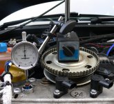
Firstly you need to get the engine at TDC. If you got the head off or a 16v, then its easy, you can set a micrometer on top of the piston, and crank it until you find TDC. There is a dwell period where the crank can move a few degrees with no piston movement at the top of the stoke. If your reduilding an engine its best to get this 100% so a read HERE is worth a read.
Of course if you have factory TDC marks on the crank, feel free to use them. however I didn't and found mine like so:

This only really works on the 16v though. If you need to do it on an 8v head, then you have to remove it to get it 100%.
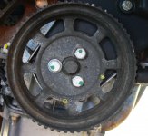
Once at TDC, you need to permanently mark the alternator pulley and the block......these are always fixed, so a perfect place to mark. Here you can just about see the two marks I made that correspond to TDC:

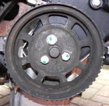
now you know exactly where TDC is on the crank, you have to do some counting. You need to count the number of teeth from the missing teeth, to the tooth under the VR sensor. You can never get this 100% though hence the need to check with a timing light once finished

Here we can see the sensor sits between teeth 17 and 18.
Now for the maths part
60 tooth wheel with 2 missing teeth is what ours are. 360 in a circle, so 360/60 = 6 degrees per tooth of the wheel.
Now to make it easy, plug the tooth number and details into the attached spreadsheet, and these are the details you put into Megatune/MS.
If you want an understanding of what they actually mean, just shout and I'll explain it some other night
As a rough starter...the trigger angle is already in degrees! The Triggers are in teeth (no.teethX6)
Trigger A is normal first ignition event
Trigger B is normal second ignition event
Return A and B are the cranking only ignitions events. You prob won't use or need these.
so for example if:
triger angle = 60
Trigger A = 7
Then fist ignition event is 60 + (7x6) = 102 degree's spark BTDC.
The return values don't matter as you should used a fixed angle return with VR's, not a trigger return.
This is also the reason you may see similar cars with very different triggers.....they simply have a lesser or more teeth in the wheel decoder offsetting the trigger angle.
When you get the car running and idling with these settings (they will be close enough), you need to fine tune it.
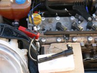
Get it warmed up and idleing, put the variable strobe on HT lead 1. If you run COP's...butcher and old lead and do the following :
:

When its idling, set the timing to a fixed 10 degrees in the spark options of megatune.....set the variable timing light to 20 degrees (double due to wasted spark ) and then see if the TDC marks line up....they will probably be at least a few degrees out.
Then adjust the trigger value until it pulls it in to the correct timing.
Then rev the car a bit, make sure it doesn't move at all (if it does your VR is prob wired backwards).
Set timing to fixed 15 degrees and strobe to 30, and make sure its still spot on.
Now you have your timing and MS perfectly calibrated
Please note this is nothing to do with cam timing or mechanical advance etc. you can set these independent of the bottom end using a vernier pulley.
Hope it was of some use...turned into a longer post than I thought, and probably loads of omissions, but any questions, just ask!
Kristian
Some engines, blocks and stuff don't have accurate timing marks, and if your installing a management system and configuring from scratch its best to get this stuff right.
I only created one timing mark at TDC (top dead centre) and used a variable timing strobe to check all different angles of timing. Its far easier this way imho.
Firstly you need to get the engine at TDC. If you got the head off or a 16v, then its easy, you can set a micrometer on top of the piston, and crank it until you find TDC. There is a dwell period where the crank can move a few degrees with no piston movement at the top of the stoke. If your reduilding an engine its best to get this 100% so a read HERE is worth a read.
Of course if you have factory TDC marks on the crank, feel free to use them. however I didn't and found mine like so:

This only really works on the 16v though. If you need to do it on an 8v head, then you have to remove it to get it 100%.
Once at TDC, you need to permanently mark the alternator pulley and the block......these are always fixed, so a perfect place to mark. Here you can just about see the two marks I made that correspond to TDC:

now you know exactly where TDC is on the crank, you have to do some counting. You need to count the number of teeth from the missing teeth, to the tooth under the VR sensor. You can never get this 100% though hence the need to check with a timing light once finished

Here we can see the sensor sits between teeth 17 and 18.
Now for the maths part
60 tooth wheel with 2 missing teeth is what ours are. 360 in a circle, so 360/60 = 6 degrees per tooth of the wheel.
Now to make it easy, plug the tooth number and details into the attached spreadsheet, and these are the details you put into Megatune/MS.
If you want an understanding of what they actually mean, just shout and I'll explain it some other night
As a rough starter...the trigger angle is already in degrees! The Triggers are in teeth (no.teethX6)
Trigger A is normal first ignition event
Trigger B is normal second ignition event
Return A and B are the cranking only ignitions events. You prob won't use or need these.
so for example if:
triger angle = 60
Trigger A = 7
Then fist ignition event is 60 + (7x6) = 102 degree's spark BTDC.
The return values don't matter as you should used a fixed angle return with VR's, not a trigger return.
This is also the reason you may see similar cars with very different triggers.....they simply have a lesser or more teeth in the wheel decoder offsetting the trigger angle.
When you get the car running and idling with these settings (they will be close enough), you need to fine tune it.
Get it warmed up and idleing, put the variable strobe on HT lead 1. If you run COP's...butcher and old lead and do the following

When its idling, set the timing to a fixed 10 degrees in the spark options of megatune.....set the variable timing light to 20 degrees (double due to wasted spark
Then adjust the trigger value until it pulls it in to the correct timing.
Then rev the car a bit, make sure it doesn't move at all (if it does your VR is prob wired backwards).
Set timing to fixed 15 degrees and strobe to 30, and make sure its still spot on.
Now you have your timing and MS perfectly calibrated
Please note this is nothing to do with cam timing or mechanical advance etc. you can set these independent of the bottom end using a vernier pulley.
Hope it was of some use...turned into a longer post than I thought, and probably loads of omissions, but any questions, just ask!
Kristian
Attachments
Last edited:

