Technical Is it possible to install a USB 12v socket?

Currently reading:
Technical Is it possible to install a USB 12v socket?

turbo500

Member
Joined
Mar 20, 2013
Messages
251
Points
118
I've tried reading around, and some people have installed a cigarette lighter, however I wanted to know how and if it's possible to install a system like this to a standard 500?
61ygxK5VJ3L._SL1000_.jpg


I've not had a chance to do any electrical work, so if anyone would be kind enough to slowly :)D) explain how I can wire this up, I'd really appreciate it!

Ideally I would like to use this to charge a powerbank to run a dashcam and charge a phone.

Thank you!
 
I don't know about which wire to use on the 500 (need to do it too) but I installed one on my scooter a while ago straight on the battery. I figured it would be ok since I use it quit frequently -aka I was lazy.
But the socket had a red LED on it and it would drain the battery in less than a week if I was not using the scooter.
The 500 battery is bigger of course but if you don't use it for a while or if you don't use a maintenance charger you will have the same problem.
So either use a socket without LED or make sure to have a switch or better it needs to be hooked up on wires/ a system controlled by the ignition key.
Good luck and let us know how it goes :)
 
Thank you

I think another member on here, mentioned using Fuse 2, and wiring it to that, since it would only work when the car turned on.

I'm just looking for a bit of a guide on how to wire it since I've never done it before. Hopefully someone can chime in (y)
 
I have fitted one where the central mounted key switch once resided.
Where do you intend to mount yours?
Wiring is very straightforward.
Black to bodywork earth
Red to fuse 2
 
Hi Andrew,

I would like to install it in the storage bin under the dash, possibly semi hidden. I know some people have created a metal mount for it as well and fixed it to the bottom of the dash.

Black to body using an existing nut or something?
 
Yup.
If you were to drill a hole for a mounting bracket- this would be ideal.
Crimp a ring terminal and tighten a 5mm bolt using a star or spring washer seems reasonable
 
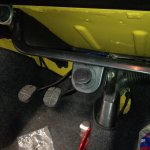
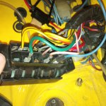
I got a little housing for a socket and put it under the tray. Fitted a piggyback blade connector and in line fuse to the live feed to the fuse box.
 

Attachments

  • IMG_20161013_222304.jpg
    IMG_20161013_222304.jpg
    1.2 MB · Views: 78
  • IMG_20161013_222144.jpg
    IMG_20161013_222144.jpg
    1.4 MB · Views: 113
Please don't take offence Cambio but i would consider a fuse box service - where the terminals are given a clean - before you start experiencing electrical oddities.
The corrosion showing in the last picture would benefit from some work.
 
Thank you both. I think that's much more clear now. I will decide what to get, I found a usb socket which has a voltage meter on it (could be interesting as an additional diagnostics tool).
 
Please don't take offence Cambio but i would consider a fuse box service - where the terminals are given a clean - before you start experiencing electrical oddities.
The corrosion showing in the last picture would benefit from some work.


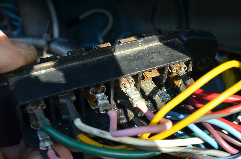
You call that corrosion/ This is corrosion, as posted previously.:D
MAL_1000 by Peter Thompson, on Flickr
Close-up photos lie; sometimes it's better to leave things which are working OK, well alone. I use "Contralube" on all electrical contacts, but still have surface corrosion. I'm sure that regular use and the incidental maintenance is what prevents my car from having electrical problems.
Shiny, as-new presentation is a good thing to aspire to, but the disturbance caused by fitting the USB socket is more likely to cause electrical problems than the rusty externals.
 
I agree with you Peter but having run classics for years my experience is that electrical maladies nearly always come down to connection issues - be it supply or earth.
The presentation is not a concern here.- just iffy circuits after having given advice......
 
To answer the original post.

-Mount the outlet wherever you want it.
-Run the ground wire to a body nut that is attached to steel. Scrape away any
paint under the nut so you have a clean steel surface.
-Use crimp on connectors on the end of all wires.
-Use black wire for the ground and red for the power.
-Red wire to fuse box, the board seems to think fuse 2. Take the fuse out and
wire to side of fuse that has no power with the fuse removed and ignition on.
-Wherever a wire passes through steel, you MUST provide some protection
for the wire. Use a rubber grommet, a short piece of fuel line, or convolute
tubing.

John
 
Last edited:
Hi John,

Thanks for the detailed reply.

So when you mention to take out the n.2 fuse, how would I wire it to the fuse box?

And for the wire passing through steel, you mean the wires going from the outlet through the body towards the fuse box?

Thanks again
 
So when you mention to take out the n.2 fuse, how would I wire it to the fuse box?

When I did this I decided that I didn't want any addition electrical load put onto the existing fuses. On my car I discovered that No. 2 fuse had an unused spade terminal, so I re-arranged the supply and load cables so that the existing cable that is live when the ignition is on and the fuse not fitted, was connected on the double terminal side of the fusebox. I fitted a female spade connector on the red cable that John suggests and this is pushed onto the second male spade. This means that the supply wire to your USB socket is not covered by a fuse and so for safety reasons you need to fit an inline fuseholder. The advantage is that you are not overloading the existing fuses and a short-circuit or overload in the USB supply will not affect any of the more important vehicle circuits.
If it is possible to sneak the red wire through an existing cable hole, already lined with a grommet, so much the better. But if you have to drill a hole I would get a small pack of grommets first and then you will know the best size to make the hole. If not used as John advised, sharp edges may gradually (or suddenly, if pulled) cut through the PVC insulation and sparks and, (depending on the circumstances), possible fire or explosion may follow.:eek:
 
Last edited:
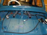
There is a little rubber blind grommet on the bulkhead between the bonnet area and the footwell. It comes out behind the knee pad inside the car. Just poke a hole through the middle of it with a screwdriver thread wire through, it's in the perfect location for wiring down to the fuse box.

You can see it in the picture below just to the right of the heater hose for the windscreen.
 

Attachments

  • IMG_4042.JPG
    IMG_4042.JPG
    1.3 MB · Views: 80
Also thinking about it there is a perfect earth close by where the flasher unit for the indicators bolts on to the body.
 
While overloading a fused circuit is something that should always be taken into consideration, a 5v outlet for a phone or Ipad should never draw more than 1 amp, and the unit shown in the first post is not going to draw more than 2 amps max. So it is okay to attach to the fused side. Something like a modern radio, auxilary lights, etc. generally needs a new circuit.

John
 
Last edited:
Peter, Vitesse, JJacob

Thank you for the replies. It's pretty much solved my initial question!

Yes the device wouldn't be pulling more than 2amps total on full load.

Also, ideally that photo of the grommet is perfect, I will check it out.

I will update this thread when I finish the install, and if I run into any issues :)
 
Hi Turbo

I am far less experienced than most of the posters here but I fitted a USB socket to my standard 500 (1970) - it looks identical to the one in your photo. With the help of Peter's fusebox photo (and a couple of message exchanges) it was actually a doddle to do and it seems to be working fine, working only when the ignition is on and recharging/running my phone/sat nav with no problem. And it has a cover so you can hide the slightly irritating blue LED when not using the socket.

The socket came with a rectangular mount and I simply used one of the holes in this to screw directly into the parcel shelf so that the socket sits inside the end of the "glovebox" where it is quite discrete (I can take a photo if you want).

For wiring I did pretty much what has been outlined so far. There was a spare hole in the bulkhead behind the fuel tank, coming out behind the steering column (my car is left hand drive) and I fed the wires through there. I obviously had to loosen the glovebox bolts to feed the wires into that. The earth I attached to one of bolts on top of the fuel tank using a ring connector crimped to the wire. The power I connected to the spare blade I also had in the fusebox like Peter (behind fuse 2) again using a connector I crimped on. The wires provided were long enough so it didn't need any additional wiring and the socket came with an inline fuse.
 
Back
Top