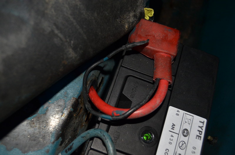
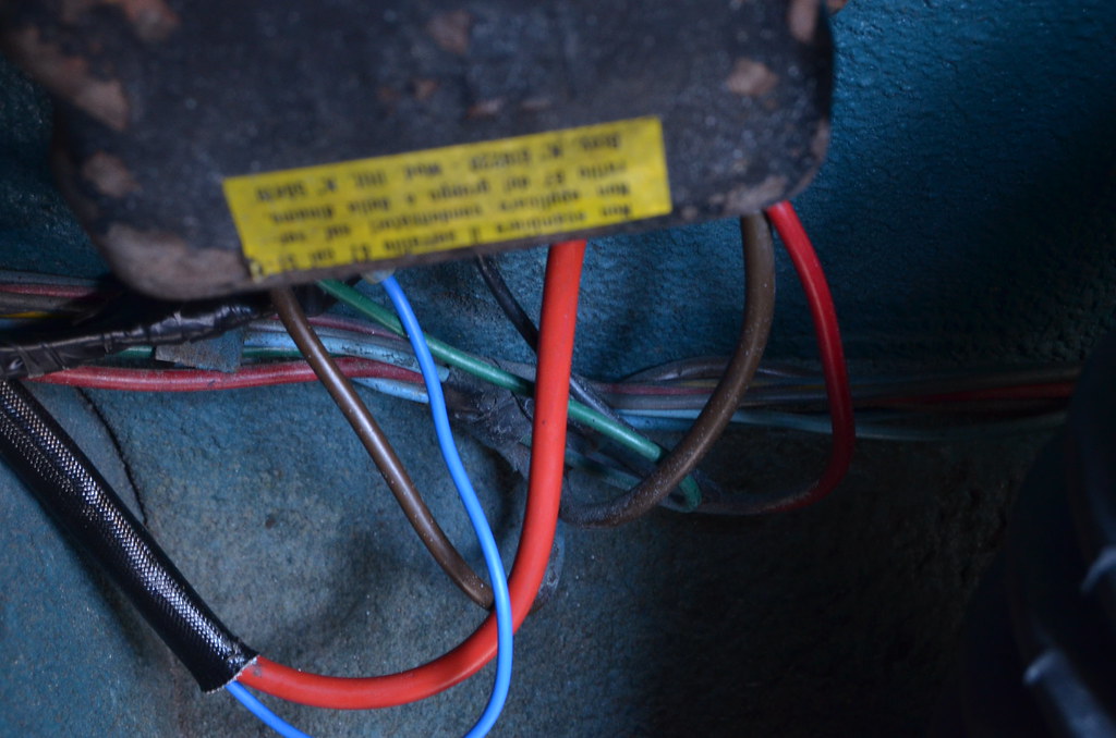
The convention seems to be that that when fitting an alternator, the output cable should be routed similarly to the former dynamo. A control box terminal is used to join to the existing cable to the starter terminal that is connected to the battery.
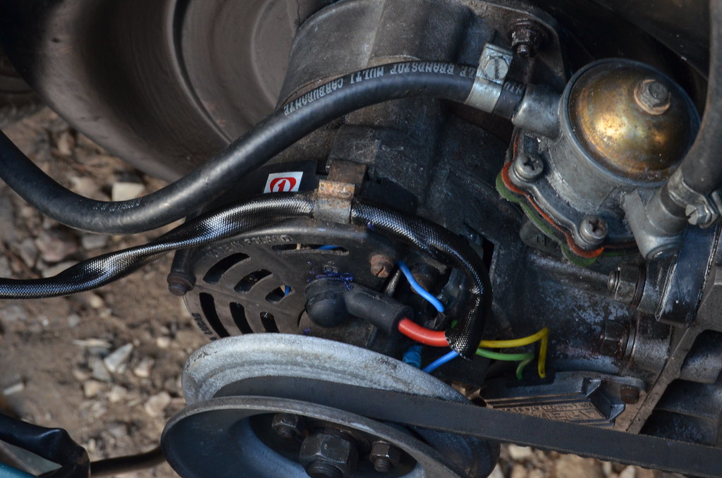
Since I have the engine and gearbox sitting on a pallet, it would be very tidy and easy to fit a cable direct from the B+ terminal and around the cowling to the starter. I think I would be well advised to sleeve the cable and I would be clipping it to the cowling at regular intervals.
Has anyone done this and what cable size should I use/ I am debating between 5mm and 6mm but for flexibility I don't want it unnecessarily thick.
")