General Fiat 500D Engine 1962

Currently reading:
General Fiat 500D Engine 1962

2. The engine breather goes down the back of the engine rather than into the air filter.


A bit of a revive of an old thread to say thanks for this amazing breakdown, I'm sure I'll be referring to it.

I came across it while looking for where in the world the crankcase breather hose goes. I know on the later models it goes into the air filter but until now I couldn't find the appropriate place. Now I know to look down the back of the engine!

Essentially mine had no breather hose, and the valve cover was spraying oil into the back of the bay! I assume this was an oversight from the former owner... anyway, another part onto the list
(side note: I take great great joy, having owned a few other old cars, in seeing how amazingly affordable it is to replace the bits and pieces on these cars!)
Glad it helped.
Hopefully it wont be too long before my engine goes back together.
Just waiting some parts to be delivered . Hint, hint...
 
Glad it helped.
Hopefully it wont be too long before my engine goes back together.
Just waiting some parts to be delivered . Hint, hint...

spend some quality time with Er indoors!!!
they are whisking their way to you as we speak...
 
Well winter is here in good old England so outside jobs have came to an end.
Time to get on with some Fiat fun.
I took a load of engine and suspension parts to a local powder coating company.
For £100 I had all these parts done and the rear suspension (arms & springs) and 4 brake back plates all coated in a black gloss.
Its not quite as shiny as 2 pack paint, but its a lot harder and more resistant to chemicals & heat.
I was really impressed with how they came out considering how bad they looked at the start.
I have just purchased a zinc plating kit, so I will hopefully start experimenting with that this weekend. Once I have done a check list of all the new nuts & washers etc I need, I will get them ordered then I can start to build the engine back together.
Hopefully I can reuse all the original bolts with Fiat on them. The only problem is a lot of them I cant remove the spring washer. They are loose on the bolt but appear to have a smaller inside diameter to the thread and just wont come off. So if I can clean them up I will try and zinc plate them with the washers in place.
 

Attachments

  • IMG_1411.JPG
    IMG_1411.JPG
    6.5 MB · Views: 29
  • IMG_1724.JPG
    IMG_1724.JPG
    2.1 MB · Views: 32
  • IMG_2250.JPG
    IMG_2250.JPG
    1.6 MB · Views: 31
  • IMG_2252.JPG
    IMG_2252.JPG
    1.6 MB · Views: 31
  • IMG_2255.JPG
    IMG_2255.JPG
    1.6 MB · Views: 33
  • IMG_2265.JPG
    IMG_2265.JPG
    1.8 MB · Views: 31
  • IMG_2264.JPG
    IMG_2264.JPG
    1.8 MB · Views: 28
  • IMG_2261.JPG
    IMG_2261.JPG
    1.5 MB · Views: 39
  • IMG_2260.JPG
    IMG_2260.JPG
    1.4 MB · Views: 36
  • IMG_2256.JPG
    IMG_2256.JPG
    1.6 MB · Views: 32
  • IMG_2268.JPG
    IMG_2268.JPG
    1.8 MB · Views: 30
  • IMG_2269.JPG
    IMG_2269.JPG
    1.5 MB · Views: 24
  • IMG_2270.JPG
    IMG_2270.JPG
    1.5 MB · Views: 34
  • IMG_2271.JPG
    IMG_2271.JPG
    1.6 MB · Views: 29
  • IMG_2274.JPG
    IMG_2274.JPG
    1.3 MB · Views: 30
In preparation for the engine build I have had a go at zinc plating some parts.
Its not as easy as I thought.
First off you need to remove as much dirt and grease as possible.
Then a good wire brush or even sandblast - sand blasting can leave a slightly rough surface which can reduce the smooth finish.
Next step a thorough soak in a caustic soda type solution.
This is where I first of all come unstuck. You then dip them in an acid bath to etch them ready for plating. Note: if its already been zinc plated then its usually best to remove the old zinc plating by leaving in the acid solution overnight. Then you need to go through the whole cleaning process again.
Then after a good wash in water, they go in the zincing bucket.
Depending on size of part/s you then have to judge what resistance you use on the current. This is rather difficult as too much and it takes ages to plate. Not enough and it can plate too quickly with poor adhesion.


Overall though I am quite happy with the outcome.
I have had to re do some of the parts. It will be interesting to see how well they cope with corrosion compared to the new parts.
 

Attachments

  • IMG_2298.JPG
    IMG_2298.JPG
    1.4 MB · Views: 30
  • IMG_2312.JPG
    IMG_2312.JPG
    1.6 MB · Views: 37
  • IMG_2297.JPG
    IMG_2297.JPG
    1.2 MB · Views: 37
  • IMG_2311.JPG
    IMG_2311.JPG
    1.5 MB · Views: 32
  • IMG_2296.JPG
    IMG_2296.JPG
    1.4 MB · Views: 35
  • IMG_2313.JPG
    IMG_2313.JPG
    1.6 MB · Views: 33
  • IMG_2300.JPG
    IMG_2300.JPG
    1.6 MB · Views: 31
  • IMG_2302.JPG
    IMG_2302.JPG
    1.6 MB · Views: 37
  • IMG_2303.JPG
    IMG_2303.JPG
    1.7 MB · Views: 34
  • IMG_2299.JPG
    IMG_2299.JPG
    1.3 MB · Views: 35
  • IMG_2308.JPG
    IMG_2308.JPG
    1.9 MB · Views: 29
  • IMG_2307.JPG
    IMG_2307.JPG
    1.7 MB · Views: 29
Last post of the year for me!!


I thought I would do a dry run of fitting the new main bearings. I bought the better quality ones this time.
Unfortunately I had a slight issue with the flywheel end bearing. It would probably be ok on the later engines that have a rubber o ring as well as a gasket. But on the D they only had the paper gasket.
You can see that the old bearing had been machined to a very small radius where it sits in the casing. The new one has a larger radius.
There is not much of a chamfer in the engine casing and even with 2 gaskets fitted the bearing housing will still not fit flush to the engine block.
So out come the 1/2 radius file and Henry the hoover and I filed the chamfer to allow for the additional radius on the bearing housing.
Finished off by adding some engineering blue to the casing, fitted the bearing and turned it slightly to make sure I had the clearance.
Just a final clean up and now I'm ready for the build.
I also completed some more zinc plating on the sump bolts and washers, cam chain cover bolts and a few other studs etc. I'm getting the hang of it now.


Just like to wish everyone all the best for 2018 and look forward to some more 500 fun.
 

Attachments

  • IMG_2322.JPG
    IMG_2322.JPG
    1.7 MB · Views: 34
  • IMG_2320.JPG
    IMG_2320.JPG
    1.6 MB · Views: 30
  • IMG_2323.JPG
    IMG_2323.JPG
    1.8 MB · Views: 33
  • IMG_2327.JPG
    IMG_2327.JPG
    1.8 MB · Views: 34
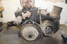
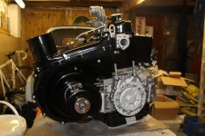
stage 1 of the engine build:
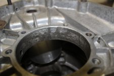
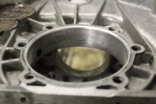
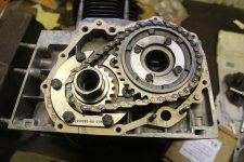
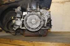
After fitting the crankshaft and main bearings successfully, the crank turned round quite freely without any tight spots. So at least the welding of the crack didn't distort anything.(y)
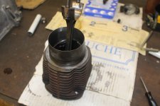
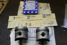
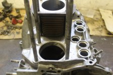
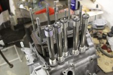
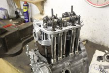
I then fitted the 2 barrels, but soon found out you cant do that on the 500 engine. Because the big ends are larger than the bore size you have to fit the pistons in the barrels first and then fit them to the block. I'm sure I didn't have this issue of the 650 engine.
The pistons were a little difficult as the bottom of the barrels are rather thin after the rebore for the 540 pistons. But I got them in eventually.
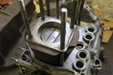
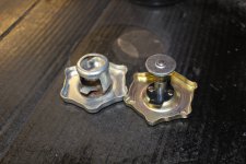
The barrels were held in place with my Fiat workshop specialist tools (a tube and a nut).
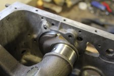
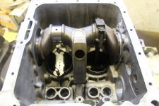
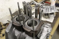
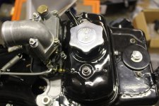
Big ends fitted and torqued up. And a quick check to make sure the crank still turns - with a good dose of oil down the bores.
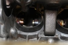
There's not a great deal of room between the bottom of the barrels and the crankshaft weight. I don't know how you boy racers get away with fitting 650 barrels?
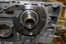
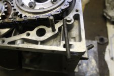
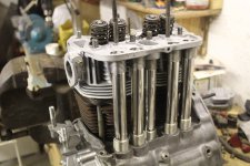
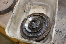
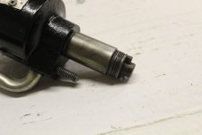
The new timing gear was fun. I had to use the old one to determine the position of the cam before fitting the chain and cam sprocket. Its daft really, the cam has 5 holes and the sprocket only has 4.
Just in case you don't have the old one at hand with any witness marks. You need to have the pistons at top dead centre then the camshaft should be sitting with the 2 lobes for N01 sitting either side of the cam follower holes. ie: if you had the rocker gear in place then No1 inlet and outlet would be rocking.
The chain sure is tight, it took quite a bit of force to get the sprocket on the end of the cam shaft.
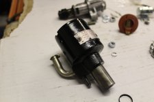
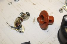
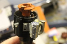
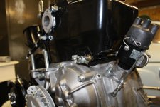
When I came to fit the oil pump and cover I came across a slight issue.
I had a choice of 2 cams - they both seemed the same to me so I fitted the cleanest one with least wear to the lobes etc.
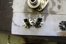
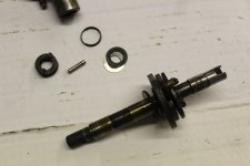
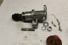
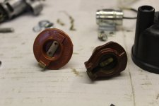
Now something I had never noticed until now was there are 2 types of drive for the oil pump - one is 6mm across flats, the other is 7.5.
Turns out I have fitted the D one as the N,D & early F's had the 6mm one.
Lucky really because out of the oil pumps I had the 6mm one was the best one with virtually no play. I guess going by the engine when I took it apart that it had not long been rebuilt before the problem with the pickup pipe and must have had a new pump fitted then. I couldn't see any wear or damage to it so couldn't see the point of a new one.
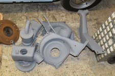
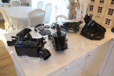
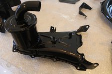
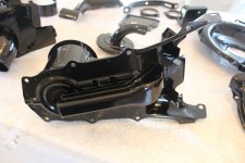
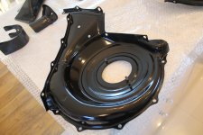
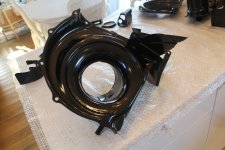
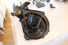
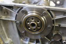
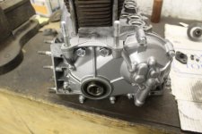
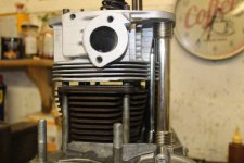
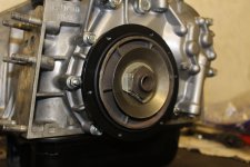
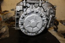
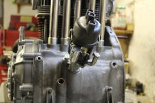
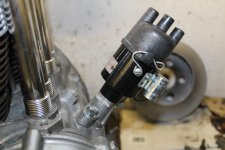
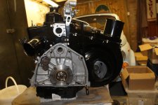
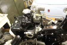
So with the cam all lined up and tabs bent over the nuts it was time to fit the cover with a new seal. I fitted the pulley in place before tightening the bolts up to make sure the seal was sitting snuggly. This has now been given a coat of paint so will be fitted soon.
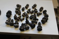
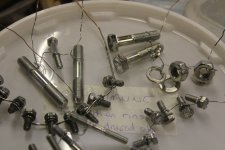
All the newly plated bolts all make it look nice and new.


Next stage, fit the pulley and then the head.
 

Attachments

  • IMG_2341.JPG
    IMG_2341.JPG
    1.7 MB · Views: 35
  • IMG_2339.JPG
    IMG_2339.JPG
    1.6 MB · Views: 33
  • IMG_2336.JPG
    IMG_2336.JPG
    1.8 MB · Views: 31
  • IMG_2335.JPG
    IMG_2335.JPG
    1.9 MB · Views: 40
  • IMG_2334.JPG
    IMG_2334.JPG
    2 MB · Views: 29
  • IMG_2331.JPG
    IMG_2331.JPG
    1.9 MB · Views: 33
  • IMG_2342.JPG
    IMG_2342.JPG
    1.8 MB · Views: 27
  • IMG_2343.JPG
    IMG_2343.JPG
    1.7 MB · Views: 30
  • IMG_2348.JPG
    IMG_2348.JPG
    1.7 MB · Views: 32
  • IMG_2355.JPG
    IMG_2355.JPG
    1.9 MB · Views: 31
  • IMG_2360.JPG
    IMG_2360.JPG
    1.8 MB · Views: 37
  • IMG_2353.JPG
    IMG_2353.JPG
    1.8 MB · Views: 28
  • IMG_2352.JPG
    IMG_2352.JPG
    1.7 MB · Views: 30
Excellent thoroughness in workmanship and explanation Sean; although I don't think that fitting a new camshaft sprocket is any sort of issue as it can only fit one way:

[ame]https://youtu.be/vztTn0GBbRk?t=35m53s[/ame]

Incidentally, this is a very new and realistic video made, I think, by a Forum member. It's good because it's done almost in real time and shows the sort of occasional stutter and gaffe that we are all prey too.:D
 
Cheers Peter, that's a good video of building a 500/126 engine.
I'm not sure about his method of tightening up the crankshaft bolt though!
He sure loves his lube!


I fitted the head tonight with some nice new valve lifter tubes.
My ones were way too rusty to reuse.
I fitted the new O-rings on the inlet valves first as when I built the head I didn't have any.
One thing I got wrong was I fitted the head studs the wrong way up.
They should have the longer threaded end screwed into the block and the short threaded end at the top. Otherwise you have about 5mm too much thread sticking out of the head. so I had to remove them and turn them over. I didn't see that in his video!
Head is all torqued down, rockers all fitted but just need to set the gaps now.


I'm not sure if that was a new block and cam chain cover all if it had been aqua blasted. Very new and shiny looking.
I decided to retain the original Patina look of the alloy casing.
 

Attachments

  • IMG_2361.JPG
    IMG_2361.JPG
    2 MB · Views: 35
  • IMG_2362.JPG
    IMG_2362.JPG
    1.9 MB · Views: 28
  • IMG_2363.JPG
    IMG_2363.JPG
    2.1 MB · Views: 26
  • IMG_2364.JPG
    IMG_2364.JPG
    1.8 MB · Views: 31
  • IMG_2365.JPG
    IMG_2365.JPG
    1.9 MB · Views: 30
I'm obviously with you all the way regarding patina. :) It starts to look even better when a bit of oil misting has been acquired, then the regular oily-rag wiping just perfects it for me.(y)

I'm not too keen on generous use of any kind of lube when assembling and I certainly wouldn't splash out on anything expensive. I balance the risk of the oil attracting grit and dirt against the highly unlikely event of there being no lubrication first startup. In fact, because I re-built the first Murf engine in the living-room, there was no more than a film of penetrating-oil at assembly.

I have always found it easy to remove the head-studs until the most recent 594 engine where they are really stuck. But I think this is the first one I have looked at which has been messed with by a previous owner.

You'll be fitting it in the bodyshell by the weekend? :D
 
Incidentally, this is a very new and realistic video made, I think, by a Forum member. It's good because it's done almost in real time and shows the sort of occasional stutter and gaffe that we are all prey too.:D

I’ve watched the videos on YouTube and they are very good (y) One very tiny detail, and I’m sure it’s an age thing with me, but so many people call nuts bolts and vice versa, stupidly I find myself getting wound up by this :spin: :mad: but Well Done to the guy who made the videos as I’m sure they will help many owners who otherwise may not have tackled their own rebuild (y)
 
One part I am really glad I saved was the oil filter/pulley.
These are really hard to find a replacement for, being the "Early prototype"
They are a complete reverse of the later type. And to be honest I can see why they changed them.
They have a steel body that fastens just like the later type, the oil flinger works the same. but the real difference is you have to remove the belt to clean the oil filter as the actual pulley part is the aluminium front cover that bolts to the body.
The other issue with this one was it was a nightmare to remove as the aluminium to steel corrosion had set in causing it to almost weld itself together.
The main body was cleaned and then put in the lathe to refinish the shaft that sits in the front seal. as with my L one it had a slight wear mark on it where the seal had worn it - I still don't understand how rubber can wear steel - or maybe its just dirt that does the damage?
The aluminium section was bead blasted, then bolted to the main body and then put back in the lathe to skim the area where the belt sits as it had seen a bit of abuse over the years.
Finally a coat of aluminium paint, sprayed the steel part black to help prevent any further corrosion and then fitted a new seal and new shiny bolts.
I had the original sump blasted, it has a few scars on it but I thought it was worth saving. Until I came to fit it:bang:
Turns out the early ones had a 78mm sump. the later ones have a 95mm sump. Only problem being my early pick up pipe was broken.
I have a couple of L/126 sump covers but they all need blasting and straightening. So for now I have temporarily fitted the D sump and left of the pick up pipe as it sits lower than the early type.
Something else to add to my next list of parts.
 

Attachments

  • IMG_2369.JPG
    IMG_2369.JPG
    1.7 MB · Views: 26
  • IMG_1448.JPG
    IMG_1448.JPG
    232.7 KB · Views: 25
  • IMG_2371.JPG
    IMG_2371.JPG
    1.8 MB · Views: 29
  • IMG_1424.JPG
    IMG_1424.JPG
    6.7 MB · Views: 37
The early distributor
My engine was originally missing its distributor when I got it so I was really pleased to be able to buy one of these last year.
Its all been dismantled, cleaned and the cast base painted.
Spring clips and screws re-plated.
New points, condenser, cap and rotor arm fitted.
Photo attached showing the difference between the D and later rotor arms.


I think these are great little distributors, with their stainless steel oil feed pipe. Internally no different to the later ones.
I just managed to save the small id plate on the side.
Although it does the job I imagine Fiat decided to change it for various reasons:
weight
cheaper to cast alloy than steel
change from 2 piece to 1 piece meant even cheaper and easier to set up


Very tempted to fit a later one or a 123, but it sure looks original!
 

Attachments

  • IMG_2382.JPG
    IMG_2382.JPG
    1.4 MB · Views: 30
  • IMG_2380.JPG
    IMG_2380.JPG
    1.4 MB · Views: 24
  • IMG_2392.JPG
    IMG_2392.JPG
    1.8 MB · Views: 23
  • IMG_2396.JPG
    IMG_2396.JPG
    1.4 MB · Views: 27
  • IMG_2398.JPG
    IMG_2398.JPG
    1.6 MB · Views: 26
  • IMG_2413.JPG
    IMG_2413.JPG
    1.8 MB · Views: 31
  • IMG_2412.JPG
    IMG_2412.JPG
    1.8 MB · Views: 26
  • IMG_2408.JPG
    IMG_2408.JPG
    1.8 MB · Views: 25
  • IMG_2403.JPG
    IMG_2403.JPG
    1.4 MB · Views: 25
The early distributor
My engine was originally missing its distributor when I got it so I was really pleased to be able to buy one of these last year.
Its all been dismantled, cleaned and the cast base painted.
Spring clips and screws re-plated.
New points, condenser, cap and rotor arm fitted.
Photo attached showing the difference between the D and later rotor arms.


I think these are great little distributors, with their stainless steel oil feed pipe. Internally no different to the later ones.
I just managed to save the small id plate on the side.
Although it does the job I imagine Fiat decided to change it for various reasons:
weight
cheaper to cast alloy than steel
change from 2 piece to 1 piece meant even cheaper and easier to set up


Very tempted to fit a later one or a 123, but it sure looks original!

I LOVE IT !!!!(y)
 

change from 2 piece to 1 piece meant even cheaper and easier to set up


Very tempted to fit a later one or a 123, but it sure looks original!


Very nice to see that in detail Sean. Having overhauled it so well I would resist temptation to put in a 123-type because you will gain nothing and lose everything. (n)

I assume you have a 126 distributor on the later car because as far as I know, all the original "F" and "L" 499cc engines have a two-part distributor and that same rotor arm; the difference in the construction is as you described and that the oiler is capped by a sprung ball-bearing
 
Last edited:
Just wanted to say thank you for everyone posting tips, photos and those videos.

We really need more videos of these technical parts for our 500's! (y)
 
Very nice to see that in detail Sean. Having overhauled it so well I would resist temptation to put in a 123-type because you will gain nothing and lose everything. (n)

I assume you have a 126 distributor on the later car because as far as I know, all the original "F" and "L" 499cc engines have a two-part distributor and that same rotor arm; the difference in the construction is as you described and that the oiler is capped by a sprung ball-bearing
I think I have one of every type now:D
But yes I have the later 126 dizzy in the L 650 engine.
I have a 126 and the L one soaking in a mixture of diesel & petrol at the moment. Might as well clean them up whilst I'm at it. Then I can strip them and do a comparison.
Don't worry there will be no mod cons on this little D.
 
Engine nearly finished!
Just the flywheel to bolt on and a few little finishing touches.
I managed to clean up one of my old sumps and paint it. I cant believe how much they have gone up since I bought the one for the L.
The quality of the new oil filler cap was terrible.
I ended up cleaning up the old one and zinc plating it. Along with a few other parts :D
 

Attachments

  • Engine Differences.JPG
    Engine Differences.JPG
    173.9 KB · Views: 35
  • IMG_2465.JPG
    IMG_2465.JPG
    1.8 MB · Views: 37
  • IMG_2469.JPG
    IMG_2469.JPG
    1.9 MB · Views: 32
  • IMG_2464.JPG
    IMG_2464.JPG
    1.8 MB · Views: 34
  • IMG_2460.JPG
    IMG_2460.JPG
    1.8 MB · Views: 35
  • IMG_2453.JPG
    IMG_2453.JPG
    2.1 MB · Views: 41
  • IMG_2456.JPG
    IMG_2456.JPG
    1.9 MB · Views: 36
Back
Top