Technical Break down of smurf !

Currently reading:
Technical Break down of smurf !

This is a photo of the alternator


View attachment 172776
IMG_1477499826.697979.jpg
 
Hi,

that B Post connector could do with some TLC as it is the main charging lead to the battery. I would suggested taking the cable off and using emery paper to clean up the faces on the terminal. I would also fit washers above and below the terminal to get the best possible contact area.
HOWEVER !!! the B terminal on an alternator is fed directly from the battery so you must remove the clamp from the negative post of the battery before you go anywhere near the B post with a spanner.
On a negative earth car always remove the negative terminal from the battery post. If you accidently touch any "live" 12V cables to the body then you won't get a short. This is a lot safer than removing the positive terminal on the battery where if you did touch any earthed part with the spanner while disconnecting it then there will be dire consequences.
BTW if you are charging a battery always switch off the charger before disconnecting as the battery will be gassing and any spark could cause an explosion.
Richard
 
Hi Richard
Thanks for those instructions, I couldn't get around to it today.
But I will check he following tomorrow and report
- ohms on coil
- Clean up b post and fit washers

- any tips on checking voltage across coil ?
- thanks for tip on removing negative and charging.

Thank you
Darryl
 
The other photo of the alternator did not load, I will put it up tomorrow
 
The original resistor and location is in the bottom middle image on this Haynes page.

Looks to be a lot of connections on that for a straightforward series resistor. Does it show how it's wired in the wiring diagram in the Haynes manual?
 
Looks to be a lot of connections on that for a straightforward series resistor. Does it show how it's wired in the wiring diagram in the Haynes manual?


Oh no....questions, questions.:D:D:D

I will need my specs for that...you know how hard those diagrams are, but a good question (which might take me all day) which I will answer.:bang:


(No it didn't!!!)

I had a careful look at the diagram but no real clue about the resistor, but it is mentioned in the text and it refers to it having a grey, inline fuse.
The following quoted from Haynes:

"On later models a ballast resistor is fitted under the edge of the luggage boot. A protective relay is fitted in the circuit. When the starter motor is operated, the ballast resistor is bypassed to allow full battery voltage through the ignition primary circuit. Once the engine is started and is running, the temperature of the ballast resistor rises,so increasing its resistance. This reduces the current flow through the primary cisrcuit to the specified voltage required for normal operations."

Plenty to chew on there....:D:D:D
 
Last edited:
Hi Darryl,

It seems to me that your problems and our joint dedication in unravelling them has revealed an issue which may have been plaguing 500 owners with later 126 engines for years,
This implies to me that the large number of these mystery problems that get reported on the Forum could be due to the fact that you really need the 126 wiring setup on the 500 with your type of ignition.
Haynes isn't always correct but what it's saying is that you must have resistor which is bypassed when the starter kicks in, has a lower resistance as the engine is cold and progressively gets more resistant as the engine and the resistor naturally warm up.
That all makes perfect sense and I think that you should at least put the resistor in just before the ignition connection to the coil. This means that theoretically you are actually taking away the advantages of this system at startup...perhaps even making it harder than it should be, but at least you are protecting it as the engine warms up when the speed of the engine will make the alternator cook the coil continuously.
We'll have to see what others offer, but apart from a big rewire, which I haven't known anyone else do, that's the best I can suggest.

Now where's me bed, I have to drive 240 miles in Murf tomorrow.:eek:
 
Got a multimeter and it doesn't go below 200 ohm, returned and got the draper version, only to try the coil and see that it also only goes to 200 ! [emoji30]
 
HI Darryl,
sorry about this long message but...
I had a look at the 126 manual a few posts above and it has an excellent description of how the ignition system works and fault finding in Section 3.
I've looked at the wiring diagram and it shows a standard distributor with a single coil and rotor arm not your rotorless wasted spark system.
I looked at the Axel Gerstil (?) site and it has half a dozen wiring diagrams none of which show a wasted spark wiring with the dreaded ballast resistor.
They do however have a picture of a standard ballast resistor which is exactly the same as old the one on my MGB which is 1.5 ohms.
Does anyone out there have a wiring diagram showing the now mythical ballasted wasted spark ignition ? If so I would love to have a look at it and determine how the ballast resistor is wired into the system.
Have a read of section 3, I can write something up but it would be pretty much what is in the Haynes manual.
I'm determined to get to the bottom of this one.
Richard
 
Hi Richard, I actually had a read of that yesterday and a lot of it goes way over my head. I have to go through your stickie proper and see if I can figure out the "generat" light !
Darryl
 
Well like Richard et al. I am determined to find a solution?:D just to muddy the waters a bit more.

It seems that what everyone thinks is a ballast resistor installed in the bonnet near the headlights is actually a dim dip resistor for the headlights. "It is in fact a headlight resister found on many models of Fiat and Lancia of the late 1980s and early 1990s. For those of you who would disagree it's part number was 82428191 and description "headlight resister'. It was fitted to UK and Ireland spec vehicles." Of course it doesn't match up with the picture from the manual that Peter posted??

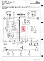
It's location would make sense to this being a fairly reasonable conclusion. See diagram below.

There are also some posts that suggests the following "The ballast resister is the wire itself that runs from the fuse box its not a component that bolts on.
Additional external ballast (wire) 1,70Ω +/-5%."

Also "Then, the powering of the coil does not depend on the fusebox. It goes straight from the battery (orange wire) through the ignition key (pale blue/black wire) to socket 28, (pale blue wire) to socket 40, (orange wire) to socket 48, then to the coil is the ballast resistor wire - the blue one".

These are from posts on the Club 126 forum taken from a Polish website, which is where a lot of 650cc engines come from.

Interesting!!!!!! I can't see how a resistive wire would dissipate the heat from the voltage drop. I assume there must be a resistor somewhere in situ?

Tony
 

Attachments

  • IMG_6324.JPG
    IMG_6324.JPG
    100.8 KB · Views: 35
Last edited:
Blown out of the muddy water.:eek:

I know I have spent too long trying browse the Internet for an answer and have read so many contradictory comments on a something that looks like a ballast resistor, smells like a ballast resistor, sounds like a ballast resistor? But it could be a dip dim resistor I am totally lost. I wish I had a 126 parked outside with one fitted, as it would take about 5 minutes to find out what it really is.

The vast majority of posts, on other forums, I have read indicate that a dry twin coil needs a resistor on the + LT side. Axel Gerstl recommend using one. Ricambi in Holland, if you select the dry coil, related products comes up below with resistors.

Simple solution if in doubt buy a resistor of eBay for £4 try it, if it works ok, great, peace of mind. Alternatively remove the distributor and fit a 123 distributor and Bosch Blue coil!!!!!!!
 
Alternatively remove the distributor and fit a 123 distributor and Bosch Blue coil!!!!!!!

That's more or less what I was going to say earlier.(y) But Darryl has already spent his pennies.:(
It's taken a lot of research to persuade me but I'm coming round to seeing the practical, mechanical reasons why an electronic distrbutor has the upper hand. The VW people seem to swear by them too. It's not just about them being maintenance-free and not needing points or a condenser. If I had been supplied with the spacer I would have tried the one I bought for the 650 on the 500. But it's still running amazingly well on points...over 200 miles today and the same planned for tomorrow.
Today's issue...a slight whiff of petrol getting very slowly worse; traced to the two rear screws on the carb top being slightly loose.I used an offset screwdriver to sort that one.
 
Back
Top