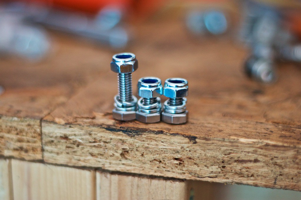
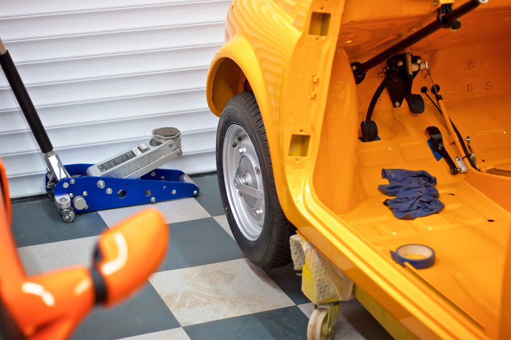
Colour-co-ordinated axle-stands?!?!
I have them too, but they multi-co-ordinate with all of the cars and bits I have ever painted.
Haha no, we've had them for years


Colour-co-ordinated axle-stands?!?!
I have them too, but they multi-co-ordinate with all of the cars and bits I have ever painted.


Hi all,
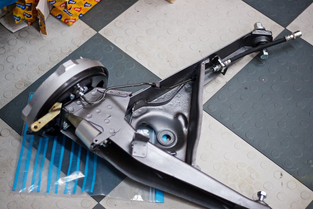
Some progress on the little Fiat but we have run into a frustrating issue. We have wired the car up as per the wiring diagram with a brand new loom. Everything seems good, no spare wires, all connected up ok but we have an odd issue as the car seems to be dead. No lights, no courtesy light etc. We have tested and verified that the lights themselves work and the car has a new earth strap from the alternator to the body and we get good earth continuity throughout the body where we have tested (for example, if I take the + from the battery to the back of the lights they work) therefore, I assume the car is well earthed.
There are no doors on yet so the door switch is closed yet there is no power to the courtesy light wire and we get no lights on the dash (she's an L) on turning the ignition key.
We have checked the the continuity on the starter cable also.
We haven't tried to start the engine yet, the fuel is yet to be plumbed in.
Does anyone have any suggestions on what might be the issue? Any help greatly appreciated
Thanks,
Katie
The power for all the ancillaries, lights etc comes via the starter motor fed by the battery cable. From the starter there is a thick brown wire, that joins to the battery cable terminal on the starter, to the voltage regulator terminal 30. I would check there first to confirm you have 12v’s to earth? It’s not switched via the ignition it should be a permanent 12v’s?
If you have 12v’s there go to the next point which is from terminal 30 on the VR to the fuse box via a red wire. It should be the first fuse and have another red wire joining it on the same side of the fuse. Check there for 12v’s to earth? The other red wire will run directly to the ignition switch, so it is an unprotected feed. If necessary check for 12v’s on that also. I suspect the 12v’s isn’t getting to the fuse box, as the one of the wires on the protected side of fuse number 1, they are two whites on my F but they maybe purple on the L goes directly to the interior light, all the door switch does is provides a short to earth when it is opened. Check on the interior light wire to earth for 12v’s or on the wire feeding it from the fuse box.
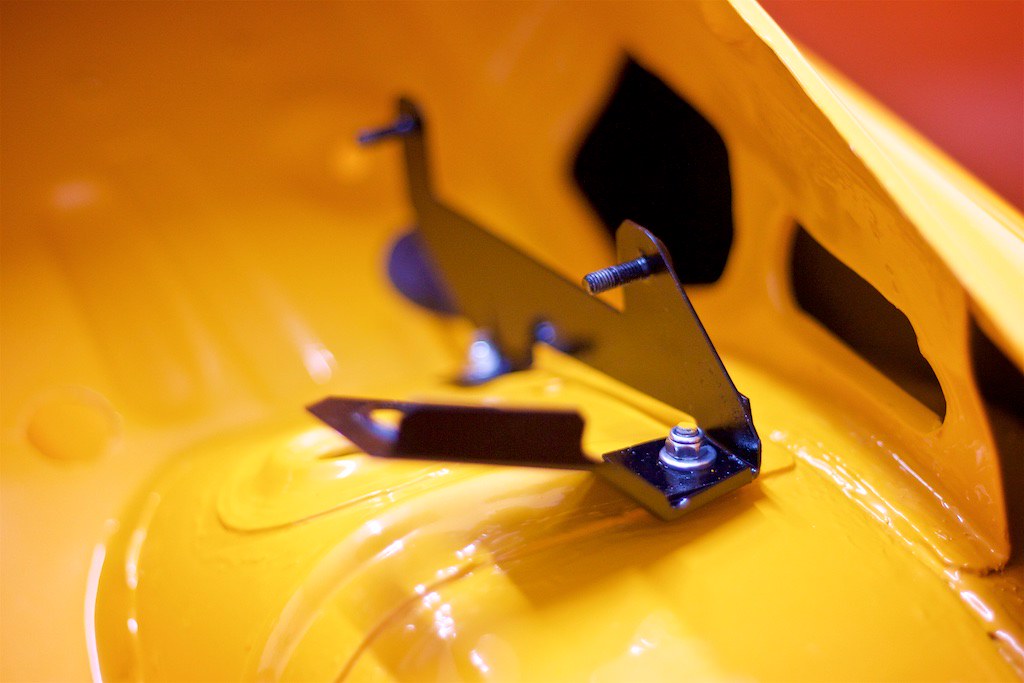
I should have mentioned that the engine is a 650cc with alternator and the starter is in a different place. The brown wire didn’t reach and so we connected it to the closer one. The loom will have to be modified slightly for it to reach I think. Thank you! Re: the rear lights - is the threaded tab earth on the top usually enough by itself as they don’t yet work.


The power for all the ancillaries, lights etc comes via the starter motor fed by the battery cable. From the starter there is a thick brown wire, that joins to the battery cable terminal on the starter, to the voltage regulator terminal 30. I would check there first to confirm you have 12v’s to earth? It’s not switched via the ignition it should be a permanent 12v’s?
If you have 12v’s there go to the next point which is from terminal 30 on the VR to the fuse box via a red wire. It should be the first fuse and have another red wire joining it on the same side of the fuse. Check there for 12v’s to earth? The other red wire will run directly to the ignition switch, so it is an unprotected feed. If necessary check for 12v’s on that also. I suspect the 12v’s isn’t getting to the fuse box, as the one of the wires on the protected side of fuse number 1, they are two whites on my F but they maybe purple on the L goes directly to the interior light, all the door switch does is provides a short to earth when it is opened. Check on the interior light wire to earth for 12v’s or on the wire feeding it from the fuse box.
:yuck:Wiring fault finding part 2:
We have got all the lights working but there is an odd set up at the front. The headlights work on both dipped and high bean as expected, but they also have an extra bulb in the bottom of the headlight that seems not to be used, and there are no wires for in my harness. I assume these are sidelights incorporated into the headlight? However, the separate sidelights/indicators below the headlights are constantly on when the ignition is on. These are the ones with the dual filament bulbs and the wiring seems also to be for dual filament (3 wires plus and earth) Is this normal? The indicators also do not work on these front lights, but The side repeaters and tail light indicators are all good.
All lights have their own good earth connections.
Can I keep it in Italian spec and still have the indicators work? Or should I remove the relevant wire and attach it to the headlight instead?
..your call, but like those joke, facsimile, Italian-style number-plates, technically illegal.