Technical To Ballast or not to Ballast

Currently reading:
Technical To Ballast or not to Ballast

Joined
Dec 27, 2014
Messages
1,134
Points
364
Location
Ripon
Greetings All,

Whilst having a root around my engine the other day I noted that the 126 'lost spark' ignition system fitted to my 500 does not seem to have a Ballast Resistor wired in???? Try as I might after further rooting here and there, in and out, front and back the damn thing is missing!!!!! Now, not having the item is one thing, but knowing where to fit a new one is another problem! I wish to avoid any damage to the dizzy contacts and the plugs so does anyone have a wiring diagram to suit and the name of a supplier - or can I do without the Ballast altogether???????? Thoughts????????

Ian.
 
A ballast resistor is fitted to the + low voltage supply to the coil. It is there to protect the coil rather than the plugs or points.

It's purpose is to keep the voltage on or below 12V's as anything greater will cook a standard coil.

What sort of ignition coil is fitted, is it a standard coil or a twin one?

Tony
 
Hello Tony,

Thanks for the message, it's a twin one from the late model 126. If I had a specific wiring digram for this coil I could identify the low volts feed and fit the Ballast - does it matter how far or close the Ballast is to the coil?? I note that in the 126 the Ballast lives in the front boot!!!


Ian.

Ian Is it the little one that looks nothing like a standard coil? As per the one in the bottom of this picture.


It doesn't matter where on the wire the resistor is placed, it's the end to end resistance of the wire you are looking to increase.

Tony
 
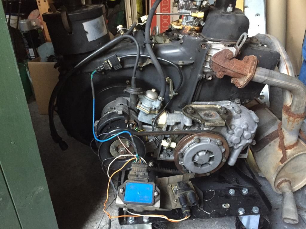
I assume you have a distributor though and not the setup shown it the picture with the blue ignition control unit shown in the picture?
 

Attachments

  • DSCN2374.JPG
    DSCN2374.JPG
    606.2 KB · Views: 96
  • DSCN2376.JPG
    DSCN2376.JPG
    625.3 KB · Views: 78
Wow that's a different setup. How does the spark get to the plugs if no HT leads?

That engine in the picture a few posts back is a 650cc engine off a really late 97 Polish built 126 that I recently bought and am currently trying to bench test. I am just getting head around how the ignition system on it works and have managed to get it to spark nice and strongly. As I was given the rear wiring loom off the car I had to extract what I needed for just the ignition and there definitely isn't a ballast resistor fitted to protect the coil, so I would say you don't need one as it has a dry coil.

If you wanted to fit one to be safe then my money would be on the red wire to the coil being the + wire to the ignition switch. If you have voltmeter you could easily find out by putting it on the red wire and switching the ignition on and off, if not just use a 12v bulb and the same thing.

Tony
 
Tony,

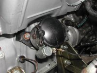
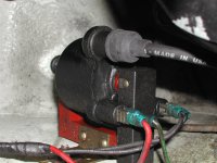
If you look at the coil photo you will note that the HT leads only run together from the coil to the plugs, the single cable only supplies the LT pulse (signal) to the coil from the dizzy it has no other function. I also think that the system I have has been cut from a late 126 (before your model) and cobbled together in my car. I'm not totally sure if the system I have did have a resistor, might try the local fiat garage and see if they can show me the different wiring diagrams for the 126!!!

Ian.
 
Oh right Ian I see. What confused me in the coil picture is I can only see one HT lead, I guess there is another one behind it that is obscured.

Tony
 
Out of interest where is the coil mounted? Is it on the little shelf on the RHD side by the exhaust?
 
The idea of a ballast resistor is to reduce the coil voltage during normal running. Most older coils were designed to give maximal output at 12V, which they did all of the time. However, when starting the engine, the starter pulls such a large current, with a coincident voltage drop (to around 9V), that the nominal 12V coil would under perform and generate a weak spark making starting difficult, particularly in cold weather.

The solution was to fit a 9V primary coil which would give the same secondary output as a 12V coil and add a resistor in series to drop the voltage from the coil to 9V during normal running. When starting the engine, the resistor is bypassed and the coil receives the usual diminished voltage (~9V) which is now sufficient to give full output. Once the engine starts, the resistor is back in circuit so that the coil does not overheat.

Modern coils are much more efficient and have more stable output voltage with a variable input voltage so external ballast resistors are not needed.

The ignition setup in the picture is the 'wasted spark' ignition common on later model Polish air-cooled Fiats. The small domed 'distributor' contains points and advance mechanism and only switches the primary current. The coil has a twin output that fires the spark plugs simultaneously - one on the top of the compression stroke and the other (wasted) on the top of the exhaust stroke. No rotors and caps to wear out, but the condensers were still a major weak point.

Chris

PS: See here https://www.fiatforum.com/500-classic/359053-650cc-engine-electronic-ignition.html for a recent discussion.
 
Last edited:
What's your take Chris on the really late Polish built 650cc engine I have recently purchased with no dizzy at all. I know you are not familiar with it but am a bit of a loss as to why when I turn the engine over using the starter motor I get a really good spark on both plugs at the same time but when I manually turn the over using a spanner on the end of the alternator nut ie fan shaft I get nothing?

A suggestion is that the ignition control box/ECU will only kick in at a certain RPM? If it works as I think it does then it is a really efficient way of producing a well timed spark and a huge spark that seems to be produced, with very little adjustment for ignition timing. I will hopefully find out tomorrow as I have just resolved an issue with a solenoid fitted to the carb that cuts fuel off when no 12v supply is available to it.

Tony
 
What's your take Chris on the really late Polish built 650cc engine I have recently purchased with no dizzy at all. I know you are not familiar with it but am a bit of a loss as to why when I turn the engine over using the starter motor I get a really good spark on both plugs at the same time but when I manually turn the over using a spanner on the end of the alternator nut ie fan shaft I get nothing?

Hi Tony,

Do you have the ignition on when you turn the engine over by hand?

For the early 1980s, it sounds like it could be an old style capacitor discharge ignition (CDI) that uses a magnetic pickup on the crank pulley to switch the output to both cylinders - another wasted spark setup. These were cheap to make, not particularly robust and when the CDIs were working properly they emitted a high pitched noise.

More sophisticated ignitions were available (eg: mid 1970s Mercedes used a nice ECU coupled to a Bosch electronic fuel injection prior to going to a more reliable mechanical fuel injection system) but probably unlikely to be used on these Polski-Fiats.

Fiat 126s masquerading as Niki 650s were sold in Oz up until about 1990. I don't think we ever got the electronic ignition, only the twin output coil & points.

Chris
 
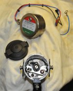
This is what the distributor looks like inside - standard really, except there is no rotor. The other item is the 123ignition conversion module for this distributor.

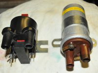
The other photo is of a new wasted spark coil next to an original one.

Chris
 

Attachments

  • Distributor.jpg
    Distributor.jpg
    331.5 KB · Views: 52
  • Coils.jpg
    Coils.jpg
    275.5 KB · Views: 48
Yes the ignition is switched on Chris when manually cranking the engine over. I don't think it is CDI, I think it is a bit more sophisticated than that. I think it is probably using transistors to do the switching inside the ignition control box. This engine is from 1997 so it relatively new in terms of 650 engines.

Tony
 
Tony, Chris,

Thank you both, I think that settles my worry because I don't need the Ballast, so no more searching or expense. Tony, the coil is mounted on the Left hand engine bay wall - opposite and above the alternator. The HT leads run up and over the cooling tinware to the plugs - cooler location maybe???

Ian.
 
Ian, thanks for the info about where the coil is mounted. I need to find somewhere to mount the dry coil and iginition control box and as I have the existing coil mounting bolts up there it makes sense to utilise them, so that I don't have to drill any additional holes.

Tony
 
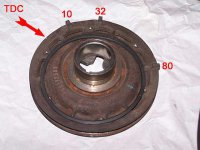
Both the 126 systems use a 12v coil so no ballast required in either. The later 97 distributorless system uses lugs on the back of the crank pulley to trigger the sensor mounted near the pulley edge, it's not possible to adjust the timing but it is perfectly accurate all the time. The engine needs a few revs to induce a signal to the sensor so it won't work when rotated with a spanner simply because it aint fast enough.
The slightly earlier distributor type setup uses a mechanical distributor with the Hall effect bits inside it replacing the conventional points so rotating the distributor can be used to change the timing just like a conventional distributor - the advantage being there are no points to wear out.

Later crank pulley has these lugs on it to set timing:
 

Attachments

  • 100_6566.jpg
    100_6566.jpg
    29.1 KB · Views: 32
The later 97 distributorless system uses lugs on the back of the crank pulley to trigger the sensor mounted near the pulley edge, it's not possible to adjust the timing but it is perfectly accurate all the time. The engine needs a few revs to induce a signal to the sensor so it won't work when rotated with a spanner simply because it aint fast enough.

Later crank pulley has these lugs on it to set timing:

So if the lugs break a magnetic field as in a Hall Effect sensor, you will need a few revs to generate a sharp voltage drop for switching - makes sense now.

High current switching transistor pairs (Darlington pairs) are usually very robust so this system should be reliable if all of the other components have also weathered well.

These systems were installed to control air pollution by allowing engines to run leaner. You need a high output coil to fire the lean mixture and coils do deteriorate over time, particularly given the harsh environment where they have to work. Yours may be OK, but if there is any doubt, replace it.

And Tony, I knew you had the ignition on, but just had to ask anyway ... sorry :D

Chris

PS: Hall effect sensors can be easily fitted to standard distributors to replace the points and condenser - two of the weak links in my opinion. The rest of the ignition system remains the same.
 
Last edited:
Back
Top